

Maintenance and Inspection Manual for Marine Gyrocompasses
⚠ Critical Safety Warnings and Operating Procedures
During the maintenance and inspection of marine gyrocompass systems, even if the main power switch is in the“Disconnect”In this state, the ship's power supply remains connected to the system distribution panel. If personnel come into contact with internal components such as terminal blocks or power units at this time, there is a high risk of electric shock. Therefore,Staff are strictly prohibited from touching any internal components.. If such operations must be performed, personnel must first disconnect the power supply at the ship's distribution panel.
staffThe use of insulation testers is prohibited.or use other instruments to directly test the system’s insulation performance. This is because such operations may damage the system’s internal electrical components. When personnel use such instruments to test relevant power distribution lines, they must disconnect the cables and wiring connected to the system in advance.
Mechanical components of the mounting and securing parts of marine gyrocompasses, such as housings and panels, may become loose due to external impacts or resonance. When loose components are detected or during scheduled maintenance, personnel should promptly inspect and retighten the relevant mounting screws.
I. Regular Inspections (Once a Day)
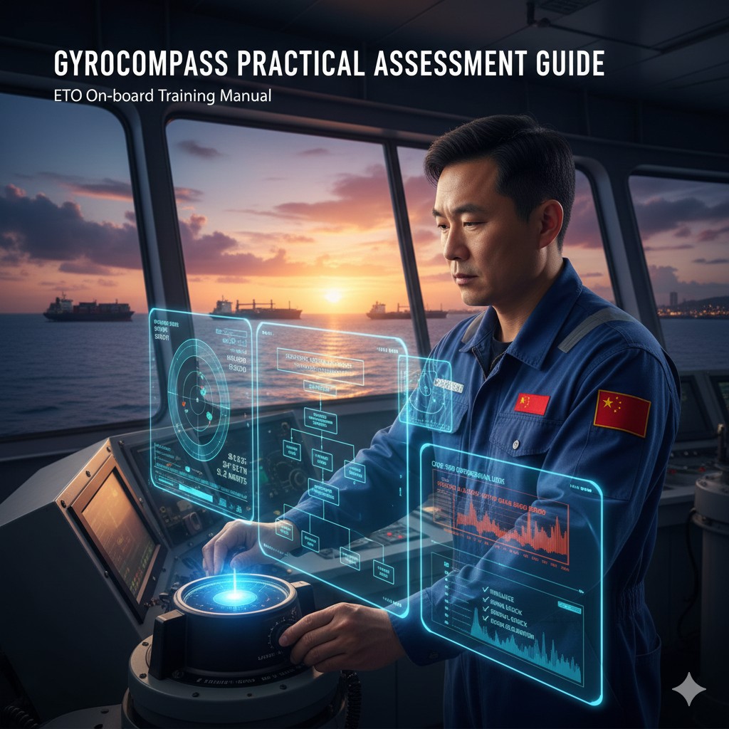
- (1) Verify eachRepeaterWhether it exactly matches the true heading displayed on the control panel.
- (2) Verify the information displayed on the control panelLatitude, Speedwhether key parameters such as these are accurate and consistent.
- (3) Inspection SystemPower Supply Voltage SpecificationsWhether it falls within the specified normal range.
- (4) Confirmation PanelIndicator lights and buzzerWhether it is operating normally and functioning properly.
Schematic of Course Consistency and Parameter Verification
II. Regular Inspections (Every Six Months/Year)
Gyrocompass Annual Inspection and Maintenance Record Form (SAMPLE)
Inspection Date: 2026 / ___ / ___
Executing Officer (ETO): _______________
| Inspection items | Technical Standards / Inspection Checklist | Result (OK/NG) |
|---|---|---|
| Safe Power-Off Verification | Before opening the enclosure, ensure that the power to the ship's main distribution panel has been disconnected. | □ |
| Mechanical Fastener Inspection | Ensure that the housing bolts, panel screws, and internal support components are not loose. | □ |
| Cable Integrity | The cable shows no signs of heat-induced deformation or damage to the outer sheath, and the shielding is securely grounded. | □ |
| Control Voltage Verification | Measure and record the output voltage of the power supply unit; it falls within the range specified in the technical manual. | □ |
| Repeater Synchronization | The error between the readings on all repeaters throughout the ship and the main compass shall not exceed 0.2°. | □ |
Common Error Codes and Troubleshooting Guide for Tuoluo
I. Table of Common Error Codes and Solutions
| Error code | Fault Description | Analysis of Possible Causes | ETO On-Site Disposal Procedures |
|---|---|---|---|
| Er 001 | Main power failure | AC power supply to the ship's main distribution panel has been interrupted; fuses F1 and F2 in the control panel have blown. | Check the power indicator light on the control panel; measure the input voltage; inspect and replace the fuse with one of the correct rating. |
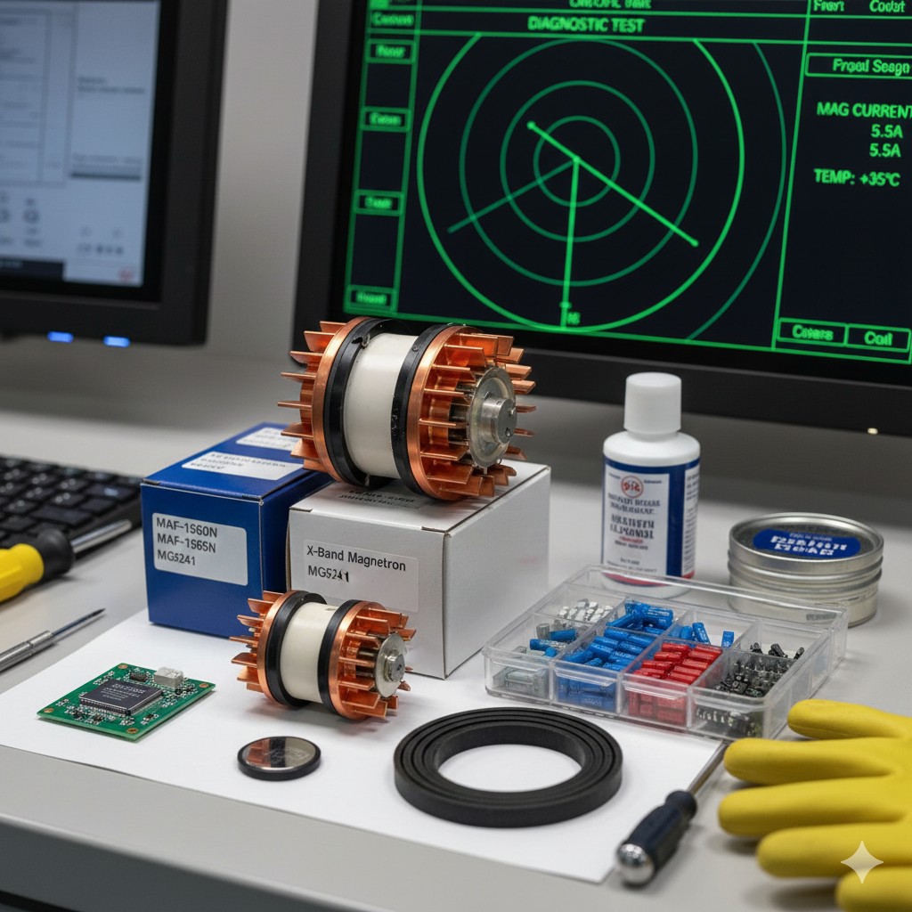
| Er 004 | Abnormal rotation speed of the compass ball | Unstable inverter output frequency; aging and wear of the gyroscope ball; excessive friction in the internal bearings. | Monitor the gyro ball current; check the power supply unit (PSU) output frequency; replace the gyro sensor if necessary. |
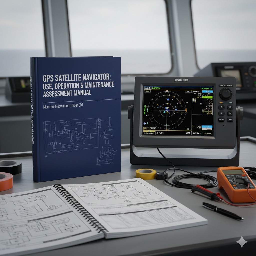
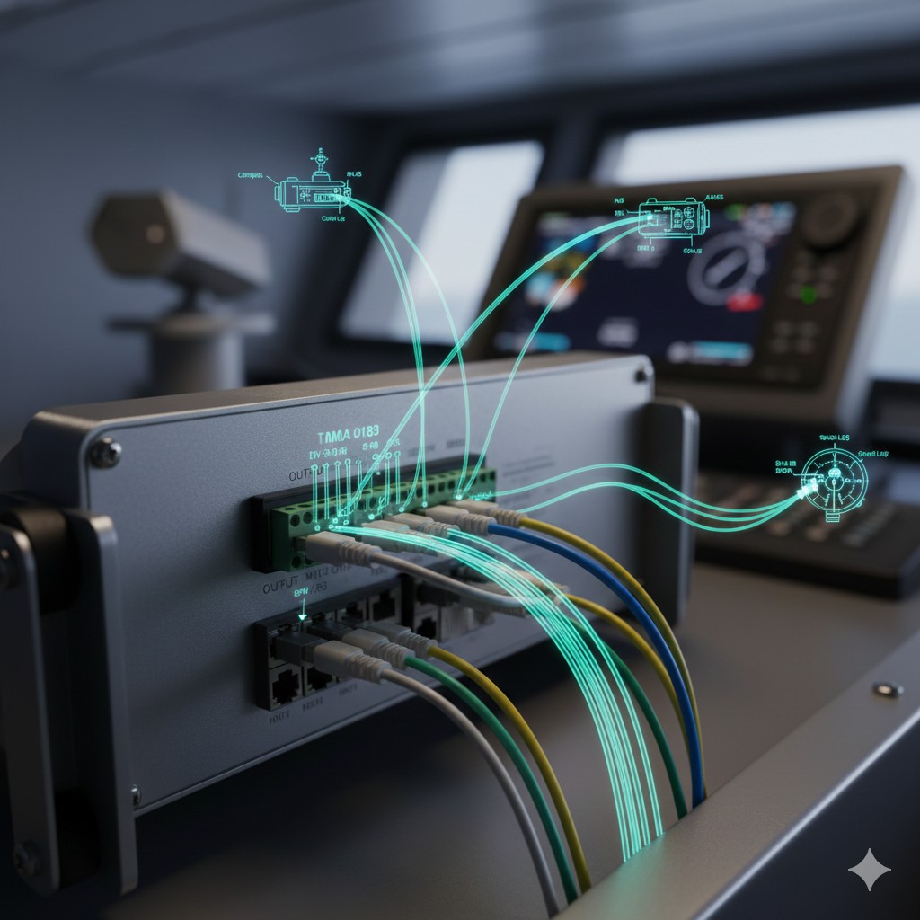
| Er 010 | GPS signal lost | Failure of the external GNSS receiver; failure to match the baud rate for serial communication (COM port); poor grounding of the shielded cable. | Switch to MANUAL latitude input mode; verify the AIS/GPS output data stream; check the signal terminals. |
| Er 022 | Repeater tracking error | Stepper motor/driver board malfunction; misalignment of the zero-point switch in the junction box. | Restart the indicator junction box; perform a zeroing operation; check the 24V step signal wire. |
II. Emergency Response Procedures During Navigation
Emergency Alert: Significant drift/loss of gyro-compass heading
- Notice to the Bridge: Immediately notify the Officer of the Watch (OOW) to confirm whether the autopilot has been switched to “Manual” or “Magnetic” mode.
- Switch data source: If the main compass fails, switch the Heading Source on the control panel to GYRO 2 (if equipped with dual compasses) or MAGNETIC。
- Manual compensation: If a loss of GPS signal causes the latitude error to become too large, immediately enter Command Mode (Code 22) Perform manual latitude compensation.
- Power cycle: If a logical deadlock occurs, obtain the captain’s approval, shut down the power for 30 seconds, then perform a cold restart and monitor the system for 5 hours to ensure it stabilizes.
III. Troubleshooting Techniques for ETO
Tips for Using a Multimeter
Measurement RS-422 serial port When measuring data, you should be able to observe the following on the DC voltage range: 0.5 V–2.5 V rapid pulsing; if the voltage remains constant at 0 V or 5 V, this indicates that the data link has been interrupted.
Key Points of the Physical Examination
Check the contents of the compass ball Compatible with liquids level and purity; check the area below the main compass Vibration-damping base Was the fracture caused by fatigue due to hull vibrations?








 Chinese
  English
  Korean
  Japanese
  Thai
Thai  Arabic
  Spanish
  Russian
  Vietnamese
  Indonesian


