
Basic operation and technical maintenance of the meter equipment
I. Structure of DS-80 Doppler Meter
The DS-80 Doppler Meter is a typical product of the DS series of meters from FURUNO Electric. It utilizes computer processing technology to provide a high degree of measurement accuracy that fully meets IMO and International Electrotechnical Commission (IEC) regulations.
The DS-80 Doppler Meter consists of a main display, sub-displays, processor, junction box, transceiver, and transducer, as shown in Figure 5-1-1.
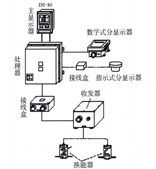 Figure 5-1-1 DS-80 Doppler Meter Machine Structure
main monitorIt assumes the functions of maneuvering and controlling the whole machine and displaying the measurement results, and the data that can be displayed include the forward/backward speed of the ship, the left/right transverse speed of the bow, the accumulated voyage, and the water depth under the keel of the ship.
processing unitThe internal components include a power supply circuit, a Doppler gate circuit and a microprocessor. Its main function is twofold: firstly, to generate trigger pulses and transmit them to the transceiver unit, thus commanding the transceiver to work; secondly, to convert the echo signals received by the transceiver into speed signals, which in turn are transmitted to the main display or other sub-displays.
transceiverThe DS-80 Doppler Meter's function is to generate electrical oscillating pulses to excite the transducer to emit ultrasound to the bottom of the ocean, and at the same time to receive the echo signal from the transducer, amplify the signal, and convert it into an electrical signal for transmission to the processor. It should be noted that some models of the DS-80 Doppler Scope Meter have the transceiver and processor integrated into one unit, thus simplifying the installation process.
split-monitorThere are two types, digital and indicator, whose signals are derived from serial data or analog data provided by the processor, and are functionally identical to the main display.
II. Basic operation and information view of the meter equipment
(i) Starting
(1) Press the “POWER” key to turn on the power, the machine first enters the self-test state.
Three “0s” will flash in the speed display window for 1 minute, and the memory, light emitting diode, and buzzer will be detected in turn. If the detection is normal, the program version number (P××) of the main display will appear in the vertical speed display window, and the program version number (P××) of the processor unit will appear in the first three digits of the voyage display window. If the detection is not normal, a corresponding error message will be indicated. Such as:1 is a ROM error, 2 is a RAM error, and 3 is an EPROM error.。
(2) Self-test is complete and normal speed and range (or water depth) display appears.
(3) Adjust the panel display brightness with the “DIMMER” control knob and press the “kt/m/s” key to select the unit of speed measurement.
(4) Press the “MODE” key to select the meter tracking mode (subsea/pelagic/automatic) and the corresponding indicator lamps G, W, A will be lit.
- Subsea tracking (G): Depth range is 1~200m below the keel;
- Water tracking (W): Depth range is 2~25m below the keel;
- AUTO TRACKING (A): will automatically switch between subsea and pelagic tracking states based on actual water depth.
(5) Press the “Distance/Keel Clearance” button to select either the range display or the under keel water depth display.Voyages are displayed in nautical miles and water depths are displayed in meters, feet, or fathoms.
(6) Preset initial voyage:The range data can still be saved after the power is turned off, and the SET key can be used to clear the range or enter the initial preset range.
(ii) Viewing of information
The main display panel of the DS-80 Doppler Meter has three display areas from top to bottom:
- At the top is the bow left/right traverse speed display area:When normally displayed, the left-arrow or right-arrow icons are illuminated to indicate the current direction of bow traverse.
- In the center is the vessel forward/reverse speed display area:The left side of this display indicates the tracking method, where G stands for subsea tracking, W for water layer tracking, and A for automatic tracking; the right side is used to display speed units, self-test status, and speed alarm messages.
- At the bottom is the voyage/under keel water depth display area:The upper part of the display indicates the status of the display, labeled “Distance” and “Keel Clearance”; the right part shows the units of the voyage.
III. Self-testing operation of the tachograph
“In the ”SYSTEM MENU 2“ you can open the ”TEST“ (Diagnostic Test): to check if the device is functioning correctly. The ”TEST" menu allows you to diagnose and check the program number. The diagnostic function checks the ROM, RAM and SIO and displays the program ID.
1. Access to the test:Press the “MENU” key to open the menu, select “SYSTEM MENU 2” (System Menu 2), then press the “ENT” key; press the “ENT” key again. Press "ENT" again. As shown in Figure 5-1-2(a), the Test Start display appears.
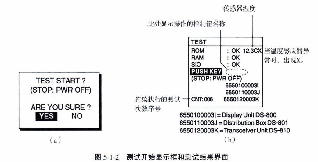 2. Commencement of testing:Press the “ENT” key to start the test. After a few moments, the display changes as shown in Figure 5-1-2(b).
3. Judgment of results:Checking that the ROM, RAM and SIO (if special connectors are used) are functioning correctly shows the following“OK” (normal) or “NG” (abnormal). The program number also appears here.
4. Cross-checking:Highlight “PUSH KEY” to prompt control check. Operate any control (except the “POWER” switch) within 5 seconds. If it works correctly, the name of the enabled control will appear on the screen. Note that if no control is operated within 5 s, the unit will automatically begin checking the LCD, and the test will repeat automatically when the automatic LCD check is complete.
5. Discontinuation of testing:To stop the test, turn the power switch off and on again.
IV. Connection of the meter to other navigational equipment
The main output peripherals and functions realized by the Marine Meter are shown in Table 5-1-1.
Table 5-1-1 List of the main output peripherals and functions realized by the Marine Meter
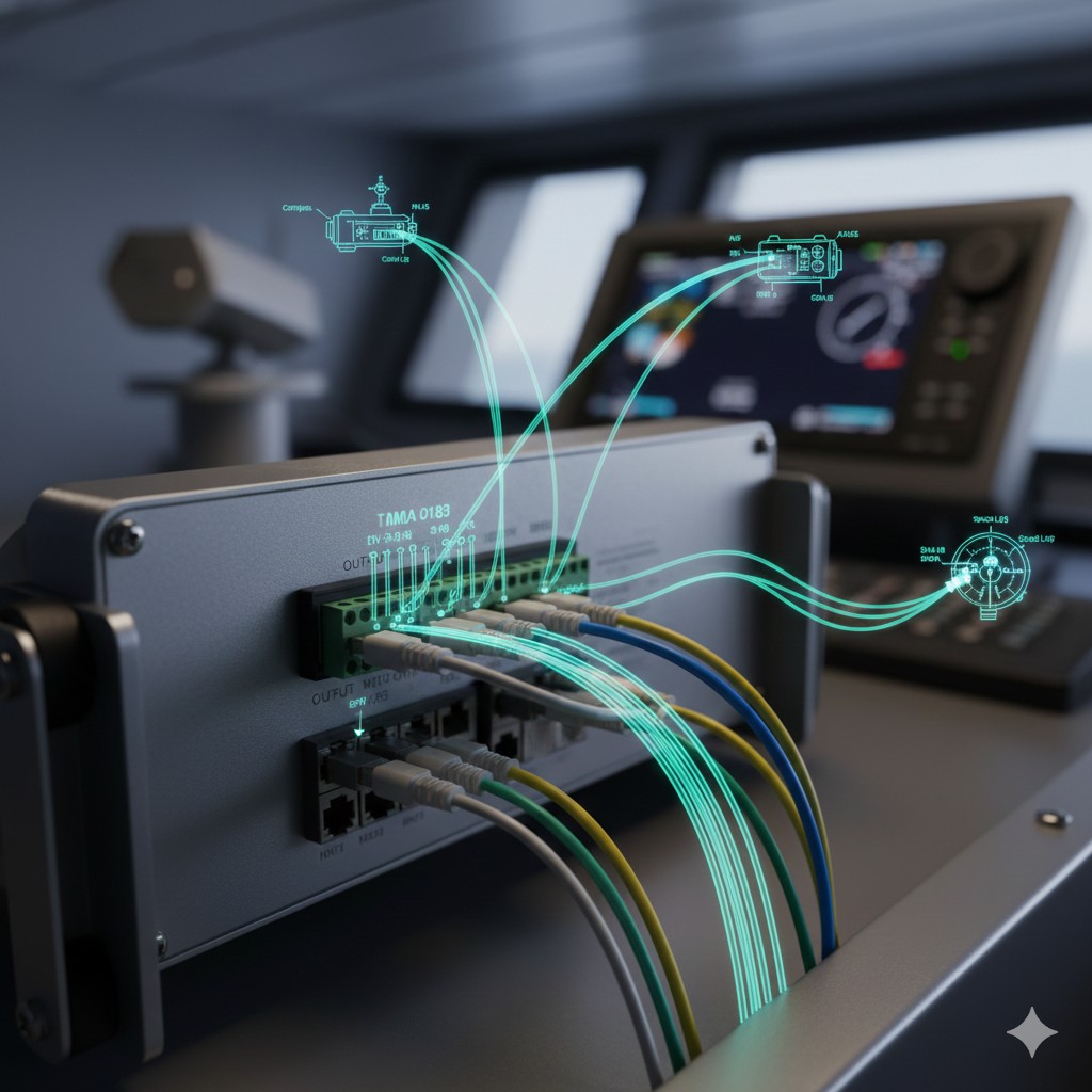
Signal Input:The DS-80 Doppler Meter is capable of accessing the GPS navigational outputs of ship's position, SOG (Speed on Ground), and COG (Course on Ground) input signals. These input signals need to comply with the IEC 61162-1 and NMEA 0183 protocolsTypical statement formats include GGA (containing information on time, latitude, precision, etc.) and VTG (including SOG and COG information). After the meter is connected to the ship's position information, the operator can conveniently check the correspondence between speed and ship's position on the display panel.
Signal output:The speed and range data from the tachymeter can be output to repeaters, electronic charts, VDRs, radars and other devices. The output signals also conform to the IEC 61162-1 and NMEA 0183 protocols, typical statement formats include:
- VBW:velocity to water or to ground. The signal output interval is 3s。
- VLW:For water voyages. The signal output interval is 1s。
- Pulse Signal:In addition, the meter's speed and range data are available in a 200 p/n mile The form of the pulses is transmitted to the radar, i.e., every 0.005 n mile outputs a pulse signal for the change in the voyage of the




 Chinese
  English
  Korean
  Japanese
  Thai
Thai  Arabic
  Spanish
  Russian
  Vietnamese
  Indonesian


