
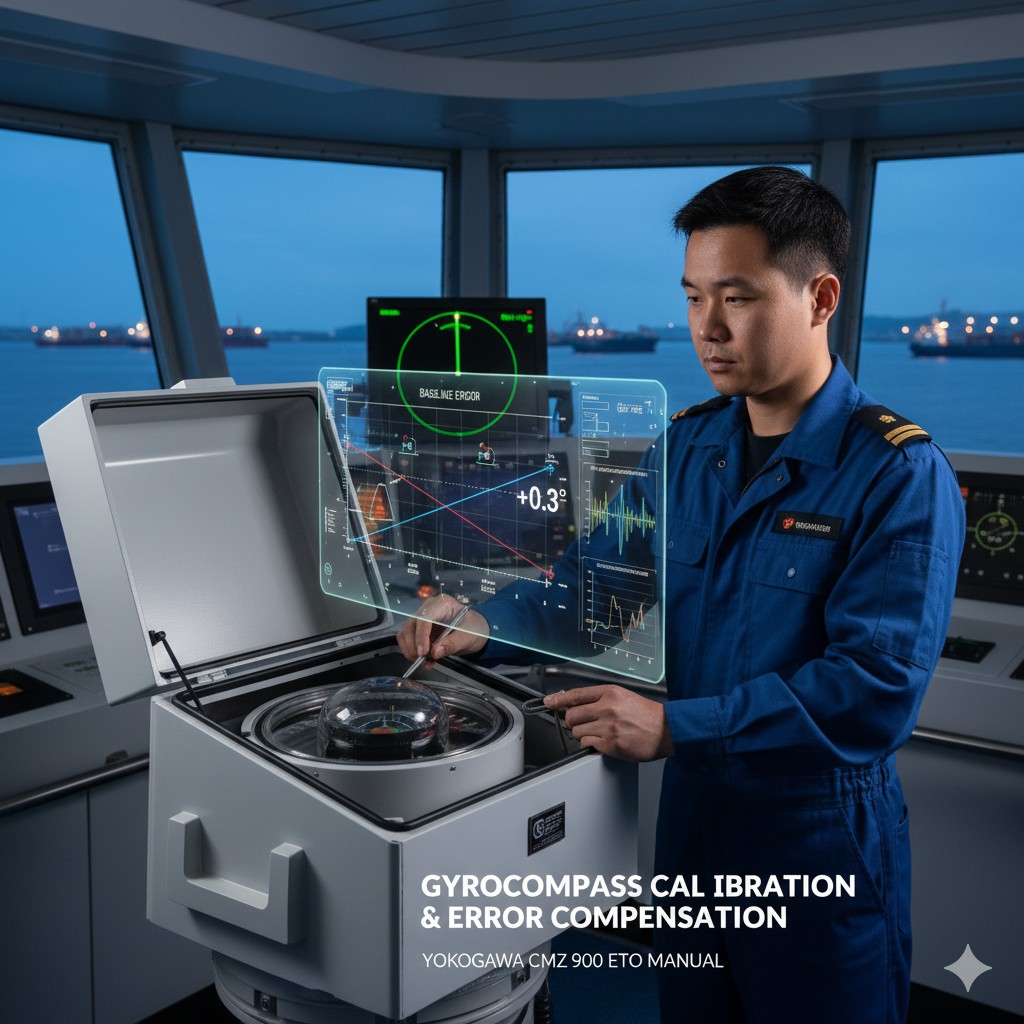
Components and Operation of a Marine Gyrocompass (Full Volume Technical Manual)
I. Hardware composition of marine gyrocompasses
The Yokogawa (YOKOGAW) CMZ 900 series marine compass is shown in Figure 4-1-1:
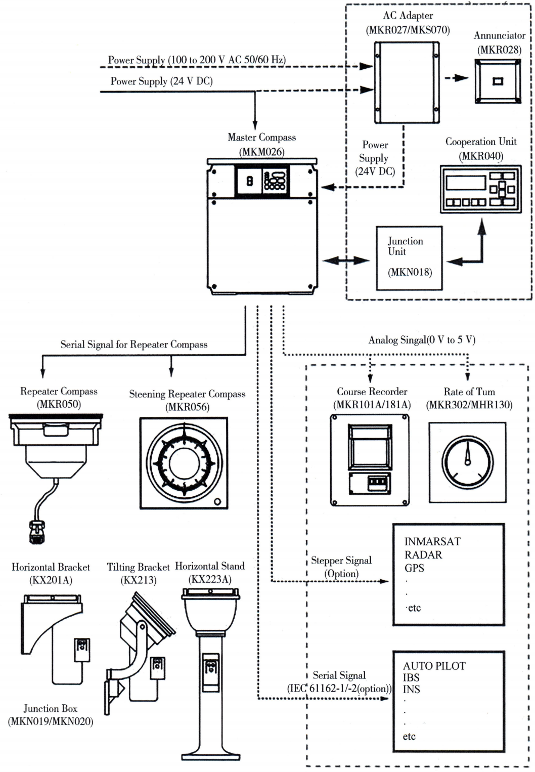 Figure 4-1-1 Block diagram of the compass system
(i) Power supply section
The power control box, shown in Figure 4-1-2, provides DC power to the main compass and converts the ship's power supply into power for the compass. The diagram indicates the location of fuses, power switches and terminal blocks inside the control box.
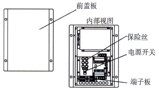 Figure 4-1-2 Power Supply Control Box Outline and Built-in Drawing
(ii) The main rosary section
The main compass is responsible for detecting the true heading of the vessel. Figure 4-1-3 Schematic diagram of the main compass shows the external and internal structure of the ship's main compass. The main compass is equipped with a power switch unit and an M-operating unit on the outside and a container for the compass ball on the inside.
[Image of a marine master compass assembly including the gyro sphere housing and digital operating unit]
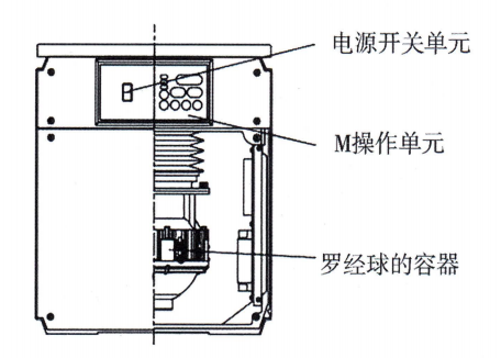 Figure 4-1-3 Schematic Structure of Main Meridian
(iii) Control box
The control box, as shown in Fig. 4-1-4, is used to distribute bow signals and power to other units and to receive other signals to the compass (e.g., speed, position, etc.). The front panel of the control box is equipped with the C operation unit, which is equipped with fuse, power switch and terminal board inside.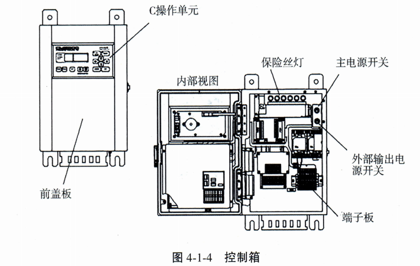
(iv) Lo Ching Repeater
As shown in Fig. 4-1-5, the compass repeater receives the bow signal from the main compass and displays the bow direction of the ship.
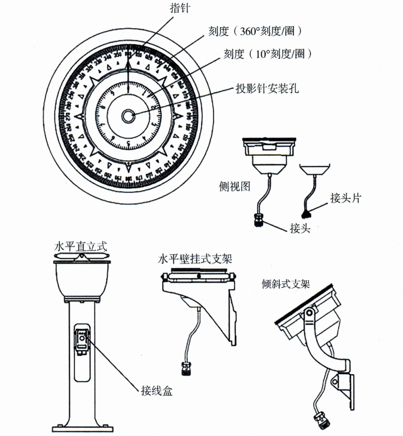 Figure 4-1-5 Robotic Repeater
Second, marine gyro compass start-up steps
(i) Confirmation that the ship's power supply to the gyro meets system requirements
Check that the ship's AC and DC power supply is normal, and check that the voltage and frequency are in accordance with the requirements for RoE power.
(ii) Powering up the control box
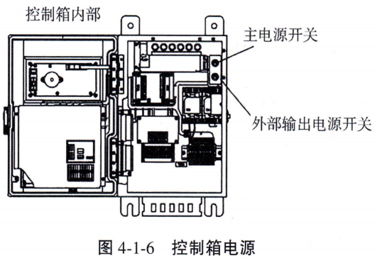
The control box power supply is located on the right side of the box as shown in Figure 4-1-6, place the toggle switch in the “ON” position power on.
 (iii) Powering up the main rosette
The main compass power switch is located on the front panel of the main compass (M operating unit) as shown in Figure 4-1-7, place the toggle switch in the “ON” position power on.
[Image of the M-type operating unit with a focus on the power toggle switch]
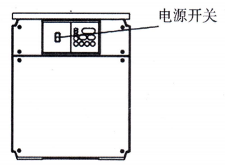 Figure 4-1-7 Main Luo Jing Power Switch
(iv) Energizing and calibrating the rosette repeater
The junction box unit of the compass repeater, shown in Figure 4-1-8, accesses bow signals and power from the main compass. These signals and power supplies are capable of driving the compass repeater. At the same time, the junction box also has the function of dimming the compass repeater. In addition, the junction box is equipped with a zero switch inside, which can be used by the operator to adjust the deviation value between the compass repeater and the main compass.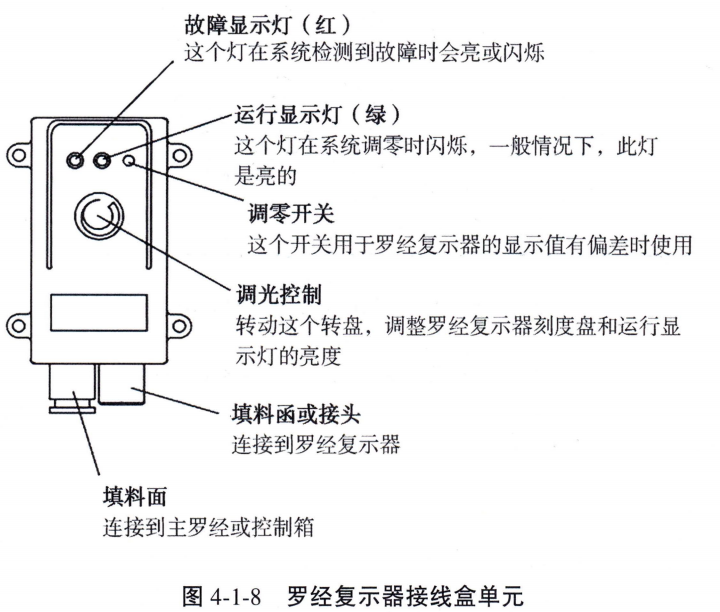
In the start-up operation of approx. 5h After that, the bow direction of the main warp is determined and the system outputs the true bow direction; the warp repeater and the stepping signal bow track the bow direction of the main warp and transfer it to the other parts or equipments that need the bow direction signal, and the starting of the warp is completed.
III. Connection of the compass signal to other equipment
To read the compass signal, you need to read the menu of C operation unit and M operation unit through the key operation menu. Figure 4-1-9 shows the functions of the keys on the panel of the C operation unit. Figure 4-1-10 shows the corresponding functions of the keys on the panel of the M operation unit.
 (i) Viewing of the compass output signal
1. C operating unit
Fig. 4-1-11 shows the panel display of operation unit C. The bow display area shows the current compass bow sounding data and system status, and the data display area shows the input method and the input vessel speed and vessel position information.
[Image of the C operating unit panel display showing heading and data areas]
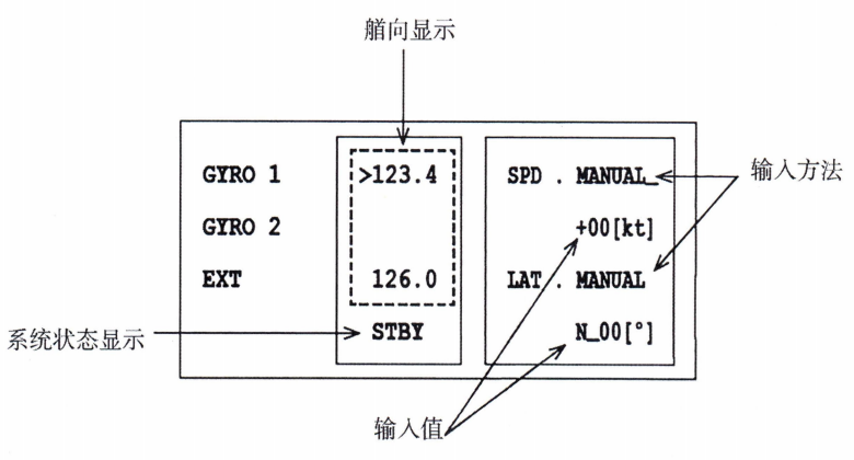 Figure 4-1-11 C Operating Unit Panel Display
2. M operating unit
Figure 4-1-12 shows the M-operating unit panel display.GYRO HEADING The data displayed in one column are the current bow output data of the compass.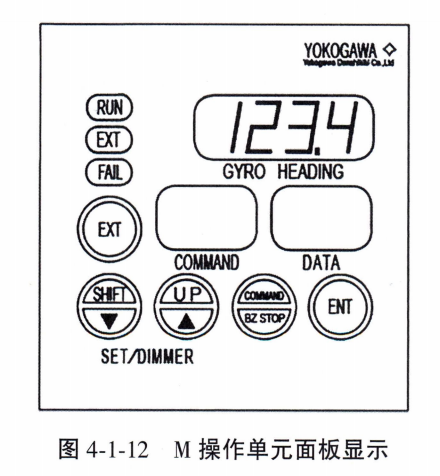
(ii) Connection of the rosette signal to other equipment
When connecting the compass output signal to radar, AIS, VDR or ECDIS, you need to modify the communication protocol of the main compass serial output port first. The specific operation is as follows: In the Command mode, find the code “Generat Menu” in the menu as 42 The “Out Port” option of the "Output Port" is used to adjust the baud rate setting of the output port, as shown in Figure 4-1-13.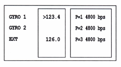
(2) Select Code in the menu “4 Generat”, press the “ENT” key to enter.
(3) Selection of codes “42 Out Port” (Depending on the specific operation screen, note: the code must correspond to the 41 or 42 shown in the illustration), press the “ENT” key.
(4) After selecting different ports by up and down keys and pressing “ENT” key, the baud rate of the selected port will start to blink, and then you can make different selections of baud rate by up and down keys, and press “ENT” key after the change is completed, the baud rate setting is completed.
(5) After the port parameters are set, connect the rosette output to the bow signal input port of the radar, AIS, VDR or ECDIS equipment through the signal cable.
IV. Methods of eliminating compass errors
The elimination of the compass error requires changing the operation mode to command mode in the C operation unit and entering the setup function to set and adjust the parameters so that the gyrocompass can correctly display the true heading. Under normal circumstances, the compass will automatically correct the speed error by inputting the ship's speed signal and latitude signal from Log and GNSS respectively.
(i) Command mode entry
C The operating unit can be switched to by pressing and holding down the command button “Command Mode”, For a diagram of the panel keys, refer to Figure 4-1-8 and Figure 4-1-9 for the labeled locations of the command keys.
After pressing the command key, the primary menu will be displayed in the data display area of the C operation unit, as shown in Fig. 4-1-14, and you can use the up and down buttons and the “ENT” key to switch menu items and enter the intermediate menu (submenu).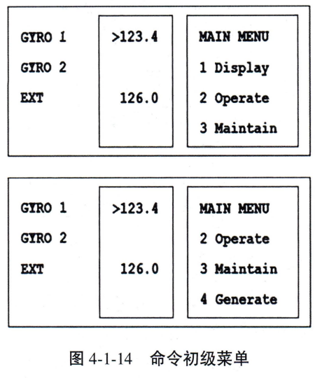
(ii) Elimination of speed errors
Speed error correction requires a command code to access the Setup Function submenu through the Command Mode. 21 SPD SET Options. The command codes for the setting function are shown in Table 4-1-1:
Table 4-1-1 Setting Function Command Code
| command code | operating unit | Function Options | Execute in wait mode | pagination | |
| C | M | ||||
| 20 | 0 | - | External bow input selection. | 0 | 42 |
| 21 | 0 | 0 | Speed setting for speed error correction. | 0 | 43 |
| 22 | 0 | 0 | Latitude setting for speed error correction. | 0 | 44 |
| 23 | 0 | 0 | The main rosary is automatically aligned. | X | 45 |
| 24 | 0 | 0 | The main rosette is manually aligned. | X | 47 |
| 25 | 0 | 0 | Sets the main compass tracking gain. | 0 | 49 |
| 26 | 0 | 0 | Displays/resets the cause of the main rosette alarm. | 0 | 50 |
| 27 | 0 | - | Display/reset (cause of operating unit alarm). | 0 | 51 |
| 28 | 0 | - | Deviation alarm setting. | 0 | 52 |
| 29 | 0 | 0 | Start Timing Setting. | 0 | 53 |
| Menu Code | Operation MENU |
|---|---|
| 21 | SPD SET (Speed error correction input) |
| 22 | LAT SET (Latitude error correction input) |
(1) Select “21 SPD SET” in “OPERATION MENU” Press the “ENT” key to switch to display speed error correction speed input.
(2) Press the “ENT” key to enter the automatic or manual input selection, at this time “AUTO” and “MANUAL” flashing at the same time, use the up and down keys to select and then press the Press the “ENT” key to enter the automatic or manual input selection.
(3) If Auto is selected, the auto boat speed input blinks, Figure 4-1-15 shows an example of the auto input display for a boat speed of 23 kn.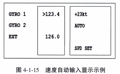
(4) If manual is selected, the ten digits of the boat speed blinks, and the boat speed can be entered manually from 00 to 99 kn by switching the digits with the left and right keys, and switching the number with the up and down keys.
(5) Press the “ENT” key after inputting the boat speed, the entered value will blink to indicate that the information needs to be changed, if the “ENT” key is pressed again, the blinking will stop and the entered number will be changed, and the correction of the speed error will be completed.
(iii) Elimination of latitude error
(1) Select “22 LAT SET” in the “Operation MENU” (Note: The original marking here is 22 SPD SET, it should be LAT SET) Press the “ENT ” key to switch to displaying the speed error correction latitude input.
(2) Press the “ENT” key to enter the automatic or manual input selection, at this time “AUTO” and “MANUAL” flashing at the same time, use the up and down keys to select and then press the Press the “ENT” key to enter the automatic or manual input selection.
(3) If Auto is selected, the automatic latitude input blinks, as shown in Fig. 4-1-16 for an example of the automatic input display when the latitude is 39°.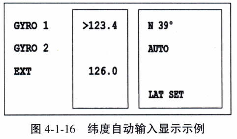
(4) If manual is selected, N and S blink and you can enter 00~70° manually by switching digits with the left and right keys and numbers with the up and down keys.
(5) Press the “ENT” key after entering the latitude, the entered value will blink to indicate the information to be changed, if the “ENT” key is pressed again, the blinking will be stopped and the entered number will be changed, and the correction of the latitude error will be completed.
(iv) Elimination of shock errors
Impact errors in gyrocompasses are caused by inertial forces generated when the ship is maneuvering (e.g., changing speed and direction). The inertia force acting on the compass system will cause the main axis to deviate from the stable position, thus generating the error. Its elimination method mainly includes the following points:
1. Design optimization and natural attenuation
The second type of shock error reaches its maximum value about 1/4 damping cycle after the end of the maneuver, and usually disappears naturally after about 1h. The general principle of eliminating the impact error is to increase the swing period of the gyro ball to reduce the effect of inertial force on the compass.
2. Compensatory law
- Extra-compensatory method:The heading reading is corrected by an external device (e.g., baseline or dial adjustment) that directly deducts the error value.
- Internal compensation method:A compensating moment (e.g. vertical or horizontal axis compensation moment) is applied to the warp to stabilize the spindle in the radial plane. For example, the Sperry MK37 model uses vertical axis compensation, and the Armabrator 10 model uses horizontal axis compensation.
When the ship is maneuvering, if the ship's latitude is lower than the design latitude, the impact error can be left untreated; if the ship's latitude is higher than the design latitude, the damper needs to be turned off to eliminate the error.
(v) Elimination of baseline errors
The baseline error of the ship's gyrocompass refers to the angular deviation between the physical baseline of the compass equipment and the ship's actual head and tail surfaces on the horizontal projection. Under normal circumstances, the zero scale line of the gyrocompass heading dial (compass baseline) should coincide completely with the projection line of the ship's longitudinal axis on the horizontal plane (representing the ship's head and tail direction). If there is an angle between the two, the heading indicated by the compass will have a fixed deviation from the ship's true heading. This systematic error will seriously affect navigation accuracy and must be eliminated by professional calibration.
There are three main reasons for baseline errors:
- (1) Installation errors:When the equipment was installed, the measuring tools were not precise enough or the installation was not done properly, and the compass base datum was not perfectly aligned with the ship's design bow and stern planes, resulting in a baseline deviation from the start.
- (2) Hull deformation effects:When the ship is under different loading conditions or encountering complex sea conditions, hull deformation will occur, such as structural bending like mid-arch, mid-sag, and so on. These deformations will indirectly cause the orientation of the compass mounting base to shift.
- (3) Loose equipment parts:Continuous vibration of the equipment during a long voyage of the ship will cause the internal mechanical parts of the compass to loosen gradually, resulting in a slow shift of the baseline over time. This error accumulates and requires regular maintenance control.
Eliminating baseline errors requires calibration according to a standardized process:
(1) Select the calibration condition:Keep the vessel in a stable condition, such as anchoring in calm waters or sailing in a straight line at low speed. Avoid lateral and longitudinal rocking of the vessel and frequent changes of course to prevent affecting the accuracy of the calibration.
(2) Obtain the datum orientation and measure the error:Common methods for determining a ship's true heading by introducing a high-precision external reference include: astronomical bearing measurements using a sextant to observe celestial bodies, interpreting the track direction by means of the Differential Global Positioning System (DGPS), and utilizing the landmark bearing rendezvous method. The difference between the compass-indicated heading and the reference bearing is the baseline error.
(3) Perform the calibration operation:Re-align the compass baseline with the ship's actual bow and stern planes, either by means of a mechanical adjustment device for the compass (e.g., azimuth calibration knob) or by entering a compensation parameter in the navigation system software interface. Once the calibration is complete, it should be verified again to ensure that the error is within the range of IMO ±0.5° Scope.
For ships in operation, it is recommended that baseline calibration be carried out in conjunction with regular maintenance cycles (e.g., each voyage or monthly). In particular, when the ship undergoes substantial load changes, structural repairs, or after a long period of high-intensity voyage, it is necessary to increase the number of calibrations in order to ensure the accuracy and reliability of the compass heading measurements.
Gyrocompass (ETO) Annual Maintenance and Utility Checklist
| Inspection classification | Maintenance operating points (according to CMZ 900) | Conformity criteria / Detailed description | Inspection results |
|---|---|---|---|
| power system | Internal Inspection of the Power Control Box (Figure 4-1-2) | Fuses are intact, terminal boards are not loose, and switches are making good contact. | □ Qualified / □ Needs to be repaired |
| Main and backup power switching test | To simulate an AC power loss, the DC 24V backup power supply should be able to switch seamlessly. | □ Qualified / □ Needs to be repaired | |
| Machinery & Installation | Inspection of main warp base and mechanical parts | Check that the mounting base is free of corrosion, internal rosette ball container leveling and mechanical fastening. | □ Qualified / □ Needs to be repaired |
| Baseline error check (Baseline) | Ensure that the physical deviation is ≤ 0.5° compared to the DGPS or astronomical bearing. | □ Qualified / □ Needs to be repaired | |
| error compensation | Automatic deskew signal input verification | Verify that the Log and GNSS speed and latitude signals are displayed as AUTO in Unit C. | □ Qualified / □ Needs to be repaired |
| Manual compensation function test | Enter command codes 21 and 22 to verify the intervention of the manually entered values on the heading display. | □ Qualified / □ Needs to be repaired | |
| signal distribution | Serial Output Port (Out Port) Settings | Verify that the radar, AIS, and VDR communication protocols match and that the baud rate blink adjustment function is normal. | □ Qualified / □ Needs to be repaired |
Gyrocompass (CMZ 900) Operation and Maintenance Assessment Questions
Applicable positions: Electrical and Electronics Officer (ETO) / Driver | Examination duration: 15 minutes
I. Technical theory and parameter verification
- In accordance with the CMZ 900 instructions, the gyrocompass shall be installed before the vessel sails. _______ Hours or more to start.
- The main loading is started and run for about _______ After hours, the main meridian bow is determined and the system outputs the true bow.
- When eliminating speed errors, if the manual input method is selected, the range of manually entered boat speeds is _______ kn.
- When eliminating latitude errors, the range of manually entered latitudes is usually limited to _______ Within degrees.
- The IMO specifies that the calibrated rosette baseline error should be kept within ±_______° Scope.
Menu operation simulation
Scenario simulation: Now you need to connect the rosette signal to a newly installed radar, write the complete command procedure to modify the baud rate of the output port on the C operating unit:
Step 1: Long press _______ key to enter command mode.
Step 2: Select Code _______ Go to the Generat menu.
Step 3: Select Code _______ Enter the output port (Out Port) setting.
Step 4: Select the port with the up and down keys to observe the baud rate _______ Adjustments are made as they occur.
Step 5: After adjustment, press _______ key to complete the setup.
III. Analysis of error elimination principle
Briefly explain the root cause of “shock error” and compare the implementation differences between the “internal compensation method” and the “external compensation method” in eliminating shock error.





 Chinese
  English
  Korean
  Japanese
  Thai
Thai  Arabic
  Spanish
  Russian
  Vietnamese
  Indonesian


