

Analysis and Troubleshooting of Short Circuit and Phase Loss in Main Circuit of Electric Motors
Forward and reverse circuits are critical in marine applications that include, but are not limited to, winchers, cargo lifters, anchors, gangways, and various auxiliary machinery such as pumps and fans. To prevent safety incidents caused by short circuits or other electrical faults, all forward and reverse circuits should be designed with interlocking mechanisms, including but not limited to mechanical interlocks as well as electrical interlocks, to ensure that contactors in both directions do not close at the same time.
I. Motor main circuit short circuit fault analysis and elimination
A short circuit is a fault condition in an electrical circuit in which current does not pass through the intended load (such as a resistor, light bulb, or other electrical device), but instead passes through a low impedance path and returns directly to the power source. Ideally, the current in a circuit should flow through all designed components, including the various electrical appliances and protective devices. However, in the case of a short circuit, the current will bypass these components and find a path of lower resistance, which usually means that the current will flow directly from one pole of the power supply to the other without passing through any or very few loads.
1. Types of short circuits
In a three-phase power system, non-normal connections occur between different phases. It can occur both on the power-using equipment and on the lines.
Unusual contact between a phase or phases of energized conductors and the ground (or a grounded metal part).
2. Causes of short-circuit faults in the main circuit
Figure 21-1 shows a motor forward and reverse circuit. In order to prevent mechanical shocks or electrical overloads caused by the inertia of the motor not stopping completely when switching between forward and reverse rotation, some forward and reverse circuits are equipped with time relays. In the diagram, it can be assumed that the KM₁ contactor is the forward contactor, the KM₂ is the reverse contactor, the SB₂ is the forward start push button, the SB₃ is the reverse start push button, and the SB₁ is the general stop push button.
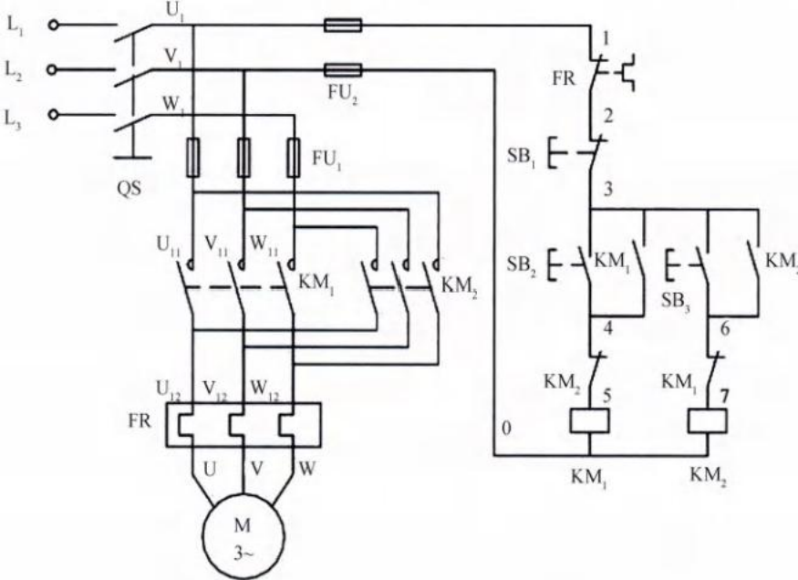 Figure 21-1 Motor Forward and Reverse Circuitry
(1) Main circuit phase-to-phase short circuit:It may occur in any part of the main circuit. u₁, v₁, w₁ Any two cables can occur without direct contact with the power-using equipment. Specific causes include:
- ● Contactor main contacts sticking:KM₁ or KM₂ main contacts are welded or mechanically jammed. If the reverse start button is pressed at this time, it will lead to a short circuit in both phases of the power supply. It can be judged by measuring whether the upper and lower ends of the contactor are disconnected with a multimeter.
- ● Interlock failure:The normally closed contact of KM₂ in the control circuit is sticking. Pressing the reversing button SB₃ while the motor is rotating forward may cause a short circuit in the main circuit.
- ● Physical factors:Loose junction box wiring, broken insulation due to vibration and friction, extremely humid environment (water in the junction box), and so on.
(2) Motor turn-to-turn short circuit:Refers to a short circuit between neighboring coils (turns) in the same winding due to insulation damage. It can cause current imbalance, overheating and mechanical damage. It can be initially determined by measuring the resistance of the three-phase windings with a multimeter to see if they are roughly equal.
Second, the motor main circuit phase fault analysis and troubleshooting
Troubleshooting Logic
Measure the voltage between L₁-L₂, L₂-L₃, and L₁-L₃. If the fuse (FU₁) is burnt out, confirm it by the power-off troubleshooting method (measuring the on-off) or the power-on troubleshooting method (measuring the upper and lower voltages).
Check for loose or broken wiring; observe contactor contacts for severe wear. A thermal relay (FR) that has a single-phase action instead of a three-phase linkage means that the thermal relay itself is faulty.
The internal winding is disconnected. To measure, disconnect the star-delta connector and measure the resistance between U₁-U₂, V₁-V₂, and W₁-W₂.
Comprehensive Maintenance Summary
Whether it is a blown fuse, a faulty contactor or a faulty thermal relay, it means that there is an abnormality in the circuit. When replacing parts, in addition to paying attention to consistent specifications, theIt is important to verify that the motor and the entire circuit are in good condition. The initial period of energized operation is focused on:
1. Motor current value;
2. Operating sounds (bearings and loads);
3. Motor temperature (focus on bearing end temperatures at both ends).










 Chinese
  English
  Korean
  Japanese
  Thai
Thai  Arabic
  Spanish
  Russian
  Vietnamese
  Indonesian

