
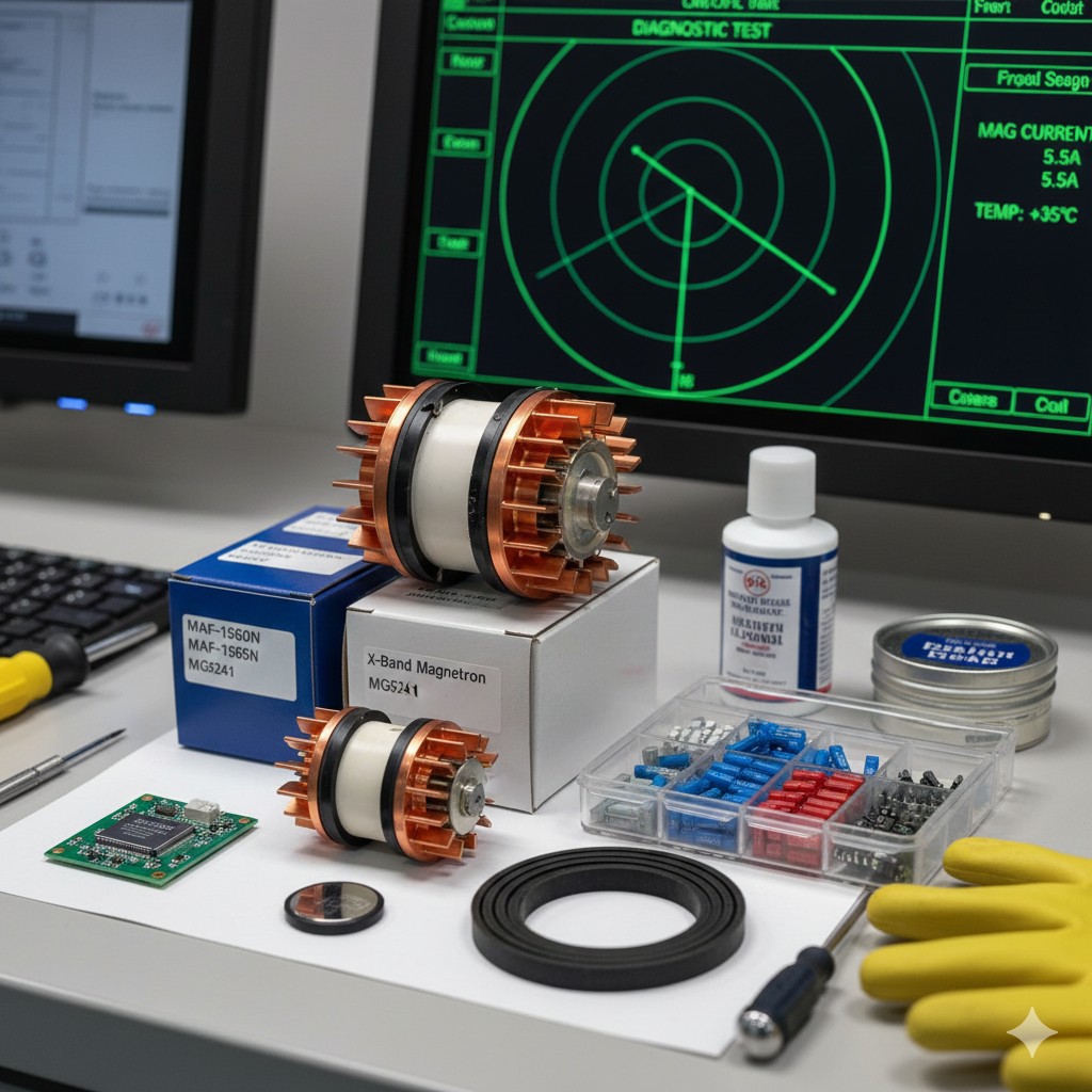
Guidelines for Assessment of Ship Navigation Radar Setup, Maintenance and Repair
I. Brief description of contents
(i) Assessment tasks and implementation
Way:Use a real radar or simulator.
Scene:The radar is normally powered on and connected to the GNSS, compass, and rangefinder signals.
Program:Candidates identify components, perform and explain self-tests, and are judged by an assessor setting up simple faults.
Time:No more than 15 minutes.
(ii) Elements and criteria for assessment
- 1. Identification and functioning of the main components of the radar.
- 2. Measurement of basic circuit parameters (safety measures, magnetron current, tuning indication).
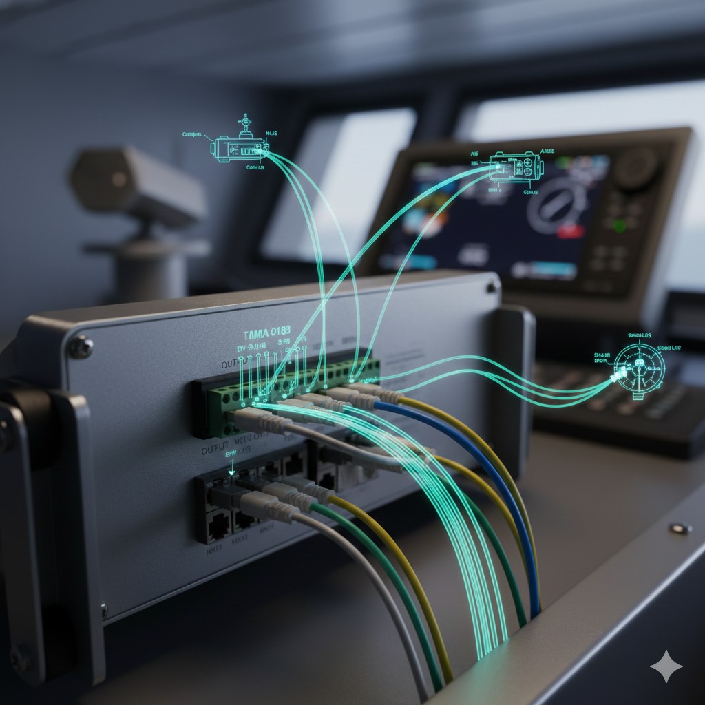
- 3. Self-test operation and interpretation of key indicators (I/O interfaces, VDR verification).
- 4. Ranging and orientation error analysis and correction.
- 5. System fault judgment, alarm elimination and emergency response.
II. Operating Methods (Furuno FAR-28×7 as an example)
Radar Evaluation Pocket Guide (ETO Pocket Guide)
1. Critical operating path (Furuno FAR-28×7)
| sports event | Menu/key path | Judgment/Action |
|---|---|---|
| priming self-test | MENU → 9 → 8 → 2 [SELF TEST]. | Confirm that the display is OK and press F1 to close |
| Initialization menu | Hold down [5:HL OFF] + Tap [1:HL OFF] | Calibration Distance (Timing) and Headers (HD) |
| Performance Monitoring | MENU → [PERFORMANCE MONITOR] | Range 24NM, observe characteristic arcs |
2. Criteria for core parameters (basis for determination)
- Magnetron current. X-band 5-12A / S-band 6-10A
- Tuning Voltage. The sweeping process shall occur 2 or more maximum value
- Equipment temperature. -40°C to +70°C
- IF Frequency. 55 to 65 MHz (60 MHz typical)
- 方位精度: The error must be controlled within ±0.5° less than
3. Preliminary Determination of Common Failures
- No image. Check Standby Status / Check Magnetron Current
- Echo Blur. Adjusting Tune / Checking for Wave Tube Fluid
- Cursor jumps. Cleaning Trackball (Isopropyl Alcohol Swabs)
- Breakwater bends. Adjusting TIMING ADJ.
⚠️ Safety Red Line (Three Principles of ETO Maintenance)
Note: This table is for evaluation sprint reference only, please follow the real boat equipment manual for detailed parameters.
Radar Failure Response Logic Mind Map
Fault occurs → Alarm processing → Quick diagnosis → Emergency recovery
Action:press a button [ACK] Key muffling and flashing → Record Alarm Code → Report to the officer on duty at the bridge.
Physical Examination:
- Check power switch and fuse
- Observe antenna rotation and noise
- Check waveguide/cable seals
Image check:
- Adjusting Gain and Tune Indications
- Switching range to check pulse width
- Confirm Standby status
Core Tools:activate (a plan) Diagnostic Test Check magnetron current (5-12A) and temperature → On Performance Monitor (PM) Evaluate transceiver performance (24 NM arcs).
Interim recovery:
- Reboot the system to save the flash memory
- Clean trackball/replace fuse
- Enable backup radar/primary and secondary switching
Professional Repair:
- Magnetron aging (abnormal current)
- PCB failure (self-test display NG)
- Report agent, provide equipment model
⚠ Principles of emergency response:Safety first, outside first, inside first, simplify first, ensure backup.
Furuno Radar Core Spare Parts List
Maintenance standards for magnetrons, fuses, batteries and wearing parts
I. Core Emission Unit: Magnetron
| Radar model/band | Common specifications | rating | Theoretical life (reference) |
|---|---|---|---|
| X-Band (12.5 kW) | MAF-1565N | 12.5 kW | 20,000 Hours |
| X-Band (25 kW) | MG5436 / MG5223F | 25 kW | 4,000 - 8,000 Hours |
| S-Band (30 kW) | MG5241 / MAF-1562V | 30 kW | 4,000 Hours |
Circuit Protection: Common Fuses (Fuse)
Fuses are located at the rear of the Processor Unit (RPU) and on the monitor power supply board, and must not be replaced with non-compliant spare parts.
- RPU Processor Unit. 10A / 15A (250V)
- MU Monitor Unit. 3A / 5A (250V)
- RPU Processor Unit. 20A (125V)
- Antenna motor power supply. 5A / 7A (125V)
III. Data retention: rosette circuit board batteries
Spare part model: CR2450 / CR2032 (depending on specific PCB version)
Replacement cycle: suggestion Every 5 years Replace once.
Signs: After power failure, the data is lost and the self-test shows “NG”.
IV. Mechanical consumables and chemicals
- Antenna Drive Belt: Check tightness (annually).
- Antifreeze lubricant: For gearing (depending on ambient temperature).
- Isopropyl Alcohol. For cleaning trackballs and rollers.
- Silica gel desiccant: Place in the transceiver case to protect it from moisture.
- Watertight seals: Antenna cover and junction box replaced after repair.









 Chinese
  English
  Korean
  Japanese
  Thai
Thai  Arabic
  Spanish
  Russian
  Vietnamese
  Indonesian

