

Operate 3-speed anchor, test and analyze overload protection action
Section I. Basic requirements for electric traction control of anchorages
The dragging control system of anchorages of all kinds of ships is basically the same, no matter it is electric anchorages or hydraulic anchorages, their technical requirements are also basically the same, which can be briefly summarized as the following points:
(1) Automatic step-by-step delayed start circuit and emergency protection circuit shall be set up in the control system of the anchor.
(2) The motor should have sufficiently large overload capacity, should be able to meet the maximum torque required for any kind of anchoring condition, and can be started under the maximum load torque, the working quota is not less than 30 min, the number of times the motor is started should not be too frequent, but to meet the starting 25 times within 30 min, and should be used in waterproof and short-term working system of the motor.
(3) motor in the blocking situation can withstand the blocking current time of 1min (blocking torque for the rated torque of 2 times), in the blocking, for DC motors, should be able to make the motor automatically to the human-set mechanical characteristics of the operation, for AC motors, should be able to automatically switch to low-speed operation.
(4) In order to meet the necessary anchor speed and pull the anchor into the hole when the low speed, the motor is required to have a certain speed range, generally required in 3:1 ~ 5:1.
(5) In electric anchoring, due to the potential energy load, the control system is required to have a stable braking anchoring function and anchor at a uniform speed.
(6) The use of combined electrical and mechanical braking in order to meet the requirements of rapid stopping and light load high-speed performance when bollarded; the electric drag device should be able to meet the requirements of being able to retract the double anchors after the single anchor breaks the ground within a given navigation area.
(7) For electro-hydraulic anchor, it should have a motor which can be driven independently, and its hydraulic pipeline should not be affected by the pipeline of other deck machinery. A clutch should be installed between the sprocket and the drive shaft, and the clutch should have a reliable locking device; the sprocket or reel should be equipped with a reliable brake, and the brake should be able to withstand the static tension of the anchor chain breaking load of 45%; the anchor sprocket wheel must be equipped with a chain brake (mechanical).
Section II Marine Anchor Control Principles
I. Read three-speed anchor control circuit diagrams
China's AC anchor widely used multi-speed variable pole squirrel cage asynchronous motor drag, 16/8/4-pole AC three-speed squirrel cage asynchronous motor, the stator has two sets of sets: high-speed 4-pole star (Y) connection, a separate set of windings; variable-pole winding, 16-pole low-speed is triangular (△) connection, 8-pole medium-speed is a double-star (YY) connection, from the triangular connection into a double-star connection belongs to the constant power speed control. The change from triangular connection to double-star connection belongs to constant power speed control. This ensures that there is a large torque at low speeds (i.e., to meet twice the rated torque to start). Medium speed 8 pole rated pole. Low and medium speeds are combined in one set of windings because of the need to convert between delta and double star connections. The control circuit for an AC three-speed anchor motor is shown in Figure 22-1. In terms of this figure, the main circuit is a typical forward and reverse plus star-delta switching circuit, KM, and KM ₂ contactor for forward and reverse switching, rationalize the line, you can find that the two contactor L ₁ and L ₃ phase connection line is exactly the same as the swap, and therefore play a role in the forward and reverse switching.
Second, three-speed anchor control circuit control system and features
Control system in the main command controller on the forward and reverse operation have three gear position, respectively to control the three gear speed, drag system design low and medium speed can be started directly, high speed to start through the medium-speed delay. Since the medium and high speeds of the motor are designed in the form of a constant rate, a protection circuit is provided in the circuit that automatically returns the motor to medium speed operation when the high speed gear is overloaded. In Fig. 22-1, this protection is reflected by the overcurrent relay KA₁(4) to reflect the load size. In order to avoid the high speed accelerating current to make the overcurrent relay operate incorrectly, a time relay KT₂ (19) is set to temporarily short the overcurrent relay. In addition, the forward and reverse rotation is a symmetrical control line, the system adopts reversible symmetrical control, using the master command controller to control the start, speed control, stop and reverse rotation of the anchor motor.
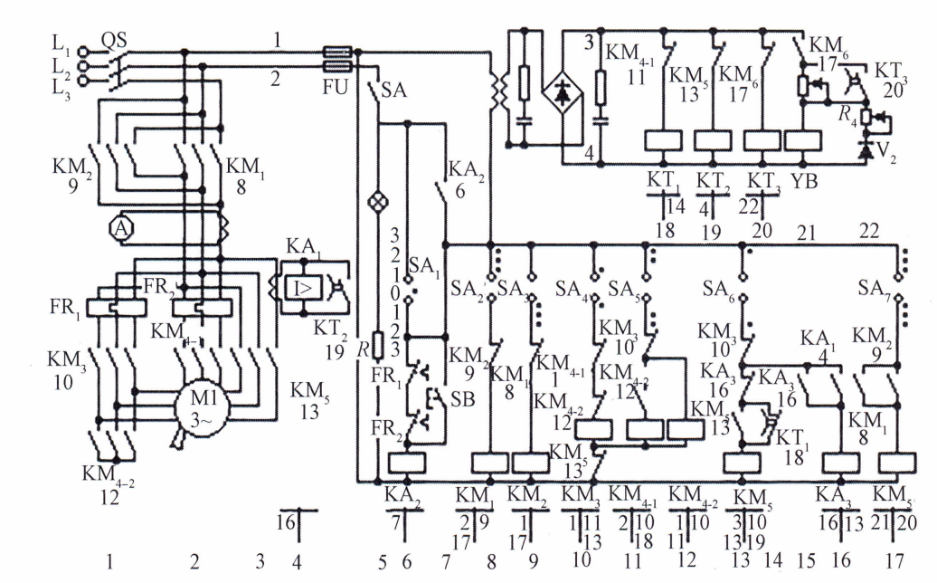
Figure 22-1 Control circuit for AC three-speed anchor motor
When the anchor motor is running in the high speed gear, once overloaded for some reason, the system can automatically switch to the medium speed gear instantaneously. After the load is reduced, if it is necessary to return to the high speed gear operation, it is necessary to trigger the main command controller handle from “high speed” back to “medium speed”, and then to “high speed” so that the anchor motor can re-enter the high speed operation. The motor can only re-enter high speed operation.
The system is provided with loss-of-voltage protection, thermal (relay overload) protection in the low and medium speed gears, and overload monitoring in the high speed winding circuit [the operating current of the overcurrent relay KA₁(4) is set to 110% of the rated current of the high speed gear]. Mechanical interlocking devices are set between the main contactors KM₁(8) and KM₂(9) and between KM₃(10) and KM₄(11, 12) of the anchor retracting and casting (forward and reverse) to prevent short circuit of the power supply. The control circuit adopts fuses for short-circuit protection.
Section III Line Analysis and Operation Guidance
I. Start-up and operation
When the main power switch QS and the control circuit power switch SA(5) are closed, the power indicator HL(5) on the main command controller panel lights up to indicate that both the main power supply and the control power supply are supplied (turned on).
(i) The master control handle is in the zero position:
The main command contact SA₁(6) closes, the loss-of-voltage relay KA₂(6) is energized, and its normally open contact KA₂(7) closes to self-locking, the control circuit is energized, and the power supply of the control circuit and the rectifier power supply are connected. At this time, the time relay KT₁(18) is energized, and contact KT₁(14) is momentarily open to cut off the KM₅ (13) circuit; KT₂(19) is energized, and contact KT₂(4) is momentarily closed to short-circuit the overcurrent relay KA₁(4) KT₃(20) is energized, and contact KT₃(22) is momentarily closed to short-circuit the economic resistor R, which is a direct current (dc) magnet. (21) is energized at full voltage. It should be noted that we have an electromagnetic brake here, here electromagnetic brake for DC form, need to be rectified through the rectifier rectifier to achieve, so when analyzing the electromagnetic brake related faults, in addition to the mechanical part of the fault, but also to consider the fault of the electrical part.
(ii) Anchor “1” block:
When the handle is triggered to the position of anchor “1” gear, the main contact SA₁(6) will be disconnected, the main contact SA₂(8), SA₄(10), SA₇(17) will be closed, and SA₂(8) will close, so that the coil of anchor contactor KM₁(8) will be energized, and the main contact KM₁(2) will be closed, which is ready for the motor to start the anchor. The main contact KM₁(2) is closed to prepare the anchor for the motor. Auxiliary contact KM,(9) is disconnected to play the role of interlock; SA,(17) is closed, due to KM₁(17) is closed, brake contactor KM₆(17) is energized, and its contact KM₆(21) is closed, the DC magnetic brake coil YB(21) gets the full voltage, and it will immediately be strongly motivated to release the brake quickly (release the motor shaft). The DC magnetic brake coil YB(21) is closed. At the same time, the time relay KT₃(20) is de-energized immediately due to the disconnection of contact KM₆(20), and its contact KT₃(22) is disconnected with a delay time of no longer than 1s, so that the economic resistor R₃ is connected to the electromagnetic brake coil circuit to reduce the heat loss of the coil current; SA₄(10) is closed, and low-speed contactor KM₃( 10) is energized, and its main contact KM₃( 10) is energized, and its main contact KM₃( 10) is energized, and its low-speed contactor KM₃( 10) is energized. SA₄(10) is closed, low-speed contactor KM₃(10) is energized, its main contact KM₃(1) is closed, the motor is anchored at low speed, and the normally closed contacts KM₃(11, 13) are opened to lock the medium-speed and high-speed contactors respectively, preventing malfunctioning.
(iii) Anchor “2” block:
When the main command controller handle is pulled to anchor “2” gear, contacts SA₂(8), SA₇(17), SA₅(11) are closed and SA₄(10) is open. Low speed contactor KM₃(10) de-energized. Medium-speed contactors KM4-2(12) and KM4-1(11) are energized one after another, and the motor is connected into a double-star shape for medium-speed operation. At the same time, time relay KT₁ (18) is de-energized because contact KM₄-1(18) is disconnected, and its contact KT₁ (14) is delayed to close for 2s, to prepare for high speed anchoring.
(iv) Anchor “3” block:
When the main command controller handle is pulled to anchor “3” gear, contacts SA₂(8), SA₇(17), SA₅(11), SA₆(13) are closed. High-speed contactor KM₅(13) is energized, its main contact is closed, another set of star windings of the motor is connected to the power supply and the motor enters into high-speed anchoring; auxiliary contact KM₅(13) is closed for self-locking; KM₅(10) is disconnected, locking the low-speed and medium-speed contactor branches; KM₆(11) and SA₆(12) are closed; and KM₆(14) and SA₆(15) are closed for self-locking. KM₆(19) open, so that KT₂(19) de-energized, its contact KT₂(4) delayed 2.5s disconnected, this time is the motor high-speed start-up of the set time, in this time contact closure in order to avoid the overcurrent relay KA₁ (4) action, the motor can not be on the high-speed, when the start-up is complete, the contact is open, so that the KA₁(4) to play the role of high-speed operation overload protection. Protection function.
(e) Directly trigger from zero position to anchor “3” gear:
If the handle of the main command controller is directly triggered to the anchor “3” gear from the zero position, then KM₄-2 and KM-1 will be energized first, and the motor will be started directly at medium speed, and then the high-speed contactor KM will be energized after the delay time of the time relay KT₁, so as to switch to the high-speed operation.
(vi) Parking:
When the master controller handle is triggered to zero position, each contactor coil is de-energized and its main contact is disconnected, at the same time, the electromagnetic brake coil is de-energized but does not brake immediately, the stored energy in the coil is discharged through the diode V₂(22) and the discharging resistor R₄, and the coil current drops to the releasing current before mechanical braking is carried out, so that the motor stops running quickly. Adjusting the resistance R₄ in the discharge circuit adjusts the time of discharge and thus the time of braking. In practice, during the process of pulling back the handle from high speed to zero position, the handle passes through and turns on the middle and low speeds in turn, the motor firstly carries out regenerative braking, the speed will have a big drop, and then after the delayed braking after the power failure, the mechanical braking is carried out at a lower speed to minimize the impact of the mechanical braking.
II. Dropping anchor
When the main command handle is placed in each gear of anchor, the working condition is the same as that of anchor hoisting, only the coil of directional contactor KM₂ is energized, and the coil of KM₁ is de-energized, so as to make the motor reversed. In addition, when anchoring in deep water, the motor enters into regenerative braking state under the dragging of anchor weight to realize equal speed anchoring, readers can analyze by themselves.
III. Main protection links
(i) Zero (loss of pressure) protection:The zero protection is realized by the loss-of-voltage relay KA₂ in coordination with SA₁. When the master handle is not in the zero position, the grid loses power, the zero voltage relay KA₂ contacts are released and the control circuit is cut off; after that, even if the power supply is restored to the grid, the system still does not work, and it must wait for the master handle to return to the zero position and for KA₂ to be re-energized in order for the system to resume work.
(ii) High-speed gear overload protection:When high speed gear operation overload, overcurrent relay KA, action, its contact open, contactor KM₅ power failure release, make KM-2, KM₄-1 successively energized action, motor switch to medium speed level operation. KM₅ power failure, its self-protection contact open, so after the disappearance of overload can not be self-electricity. If high speed operation is required, the handle must be returned from the third gear to the second gear and then back to the third gear.
(c) Overload protection for low and medium speed classes and their emergency anchoring:The low and medium speed overload protection is realized by the thermal relays FR₁ and FR₂. When the thermal relays FR₁ and FR₂ are overloaded, since the automatic reset time of the thermal relays takes about 2min, in case of emergency, if the motor still needs to run in the low and medium speed levels, the emergency button SB on the main controller can be pressed to force the motor to continue to work.
(d) Electrical interlock protection for anchoring and anchoring:The electrical interlocking protection of the anchor and anchor is realized by connecting the normally closed auxiliary contacts KM₁ and KM₂ of the forward and reverse direction contactors KM₁ and KM₄ in series with each other in the other's coil circuit.
(v) Interlocking protection for medium and low speed winding switching:Medium and low speed winding is a set of variable pole winding, in order to prevent short circuit of power supply caused by connecting to the grid at the same time, it is necessary to require interlocking, connecting the normally closed contacts of KM₃and KM4-2, KM4₋,contactors in series with each other in each other's coil circuit.
Section IV. Maintenance management of the system
Maintenance and management of three-speed AC motors and brakes can be categorized into daily inspection and maintenance, routine maintenance and overhaul:
I. Daily inspection and maintenance
The main contents of daily inspection and maintenance include: checking whether there is any foreign matter around the equipment, cleaning the appearance of the motor; checking whether there is any loosening of the foot bolts and fasteners of the motor; checking whether the motor coupling is normal; checking whether the grounding wire is well grounded; checking whether the insulation of the motor windings is normal (generally not less than 2 MΩ); and energizing the motor to check whether the suction and closure of the brake is normal. In addition, for motors with water drain holes at the bottom, the bolts should be unscrewed periodically to drain out the condensate.
II. Routine maintenance
The routine maintenance cycle is generally 6 months, and the ship can make appropriate adjustments according to the frequency of use of the equipment and the requirements of the equipment manual. Inspection includes: open the junction box, check whether the pile head wiring is loose, whether the wiring is damaged or worn out; check whether the motor watertight condition is good; measure the brake clearance, if it is too big, we should make appropriate adjustments; check whether the motor coupling connecting bolt and elastic rubber ring are normal; check whether the bearing lubricating grease is deteriorated, and add the appropriate amount of lubricating grease.
III. Overhaul
The overhaul (disassembly and inspection) cycle for motors and brakes is 3 to 5 years. When overhauling, the motor should be disassembled and cleaned. Measure the insulation resistance of each coil, if it is lower than the required resistance, it should be insulated; check whether each coil is loose, short-circuited, open-circuited, and its reliability; find that there is abrasion and overheating phenomenon in the insulation wrapping, it should be repaired; check whether there is any phenomenon of going to the outer circle and the inner circle in the bearing and rotor journal, and whether there is any abrasion between the rotor and the stator; and replace the bearings. When replacing the bearings, it should be noted that the end surface marked with the bearing code must be mounted on the outer side for easy identification during maintenance. Inspect the brake system, including brake discs, brake coils, springs, and friction pads.
Air gap adjustment of brakes and emergency measures to deal with brake failure:
(1) After long-term use of the brake, the brake parts will wear out, which will cause the air gap to increase and the working length of the working spring to increase, and in serious cases, the armature may not be able to be sucked on. The increase in the working length of the spring will cause the brake pressure to drop, so the working air gap of the brake must be checked frequently and adjusted in time.
(2) When the brake winding is not energized and the brake is to be released (i.e., the brake is not in use), the screws can be screwed out, the washer taken down, and then screwed in to push the armature toward the electromagnet and the top foot to make the air gap zero, at this time, the brake and the armature are loosened, and the rotor of the electric motor can rotate freely to achieve the purpose of artificial release.
(3) When the motor is in operation, if the brake fails, such as brake winding breakage, silicon rectifier damage, power supply disconnection or disconnection, etc., the motor will be in the braking state immediately, and then the power supply should be cut off immediately, and the load should be unloaded and overhauled. After the brake failure is eliminated, the manual release screw must be restored to its original state and the motor must undergo a test run before it can be formally used.
Section V. Precautions for the use of electric motors
I. Precautions for the use of three-speed AC motors
In the use of three-speed AC motors, the running current of the motor should be observed frequently, so as not to make it run under the condition of exceeding the rated current, and the temperature of the motor should be checked frequently, and whether there is any peculiar odor and sound should be observed, and once any abnormality is found, the motor should be shut down for inspection at once, and it should be used further only after the fault is eliminated. It should be noted that these motors are generally operated for a short period of time, and the permissible operating time for each speed of the motor is also different.
II. Maintenance and management of electrical control boxes and master command controllers
Electrical control boxes and master command controllers are another focus of electrical section management. In order to ensure that the control box works properly, the equipment must be inspected periodically. The inspection period is determined according to the difficulty of the work and the environment and location of the equipment. The maintenance of the control box is divided into routine maintenance and overhaul two kinds. Routine maintenance is carried out once a month, and major maintenance is carried out once every three months. The specific period of routine maintenance and overhaul can be determined according to the sailing time of the ship.
- (1) Remove the dust and dirt in the box; (2) Check whether the fasteners of each electrical component are loose; (3) Check whether the parts are corroded; (4) Check whether the insulation resistance of the control box is in accordance with the data specified in the technical conditions; (5) Check whether the grounding device is intact and whether the grounding screw is loose; (6) Check whether there is any damage to the wiring of the contactors and relays; (7) Check whether the contactor has a different flow of sound, such as too loud, should check the movable part, and be corrected; (8) check whether the ammeter on the main command controller works normally; (9) check whether the loss of voltage zero protection function is normal; (10) check whether the main command controller contacts of the turn-on sequence is in line with the contact chart and so on. Before overhauling, please note that the power supply must be cut off, and it is strictly prohibited to overhaul with electricity.
- (1) Clean the main contacts of each contactor and replace the damaged movable and static main contacts; (2) check and adjust the action current value of the thermal relay; (3) check and adjust the action value of the high-speed level overload protection device; (4) check and adjust the action time of the time relay; (5) check and adjust the suction voltage and maintenance voltage of the electromagnetic brake coil; (6) check whether the electrical interlock of the main contactor for forward and reverse and the mechanical interlock are normal; (7) check the main command controller for damage and cracks and measure the condition; (8) check the integrity and fastening status of the main command controller fasteners and measure the condition; (9) check the main command controller for damage and cracks and measure the condition; (10) check the main command controller fasteners for damage and cracks and measure the condition. mechanical interlock is normal; (7) check the main command controller for damage and cracks, and measure the situation; (8) check the integrity of the main command controller fasteners, fastening status is good; (9) check the main command control mechanism is flexible, there is no jamming, the contact contact is good; (10) to be in the main command controller roller and ratchet wheel and the end of the movable contacts and cams, such as friction between the friction part of the roller and ratchet wheel, as well as the tail and cam, etc., apply a appropriate amount of industrial petroleum jelly or grease.
It should be reminded that before overhauling, the power switch from the main switchboard to the control box should be disconnected, and a warning sign of “overhaul” should be hung on the corresponding position of the power switch. In addition to the above routine maintenance and overhaul, daily maintenance is also very important, to check whether there are other objects outside the box to prevent its normal cooling; whether the temperature outside the box is overheating phenomenon; in the process of work, if you find anomalies, you should immediately stop the car to check and eliminate the causes of accidents.
Three, overload protection principle analysis and test operation
The overload protection contacts are connected in series in the control circuit and cut off all contactors when triggered.
1 . Trigger conditions:When the motor current continuously exceeds the set value (e.g. 1.1~1.2 times of the rated current), the overload relay operates. In high speed gear, the overload protection sensitivity is higher (because the high speed winding current is higher and the temperature rises faster).
2. Protect the logic:In case of overload, the normally closed FR contact opens → the control circuit is de-energized → all contactors are released → the anchor stops. To reset, press the FR reset button manually or restart the system.
3. Heavy load not on high speed principle:Load detection mechanism: real-time monitoring of load current through current transformer. When the load current exceeds the threshold value (current) of the middle speed gear, the control system automatically locks the high speed gear (prohibit KM₃suction).
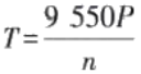 It is known that the output torque is inversely proportional to the speed in the mechanical characteristic curve of most motors (e.g. asynchronous motors). During heavy loads, the motor requires more torque, and high speeds significantly reduce the available torque, resulting in unstable operation or even stalling of the motor. High speed operation of the anchor chain under heavy load may result in splattering of paint, breakage of the anchor chain, loss of control or structural fatigue. Mechanical parts rotating at high speeds under heavy loads may vibrate due to increased inertia forces, or even resonate with the system's intrinsic frequency, resulting in structural damage.
IV. Overload protection test operation
1. Preparation:Ensure that the anchor motor is running properly with no load. Connect a clamp-on ammeter to the main motor circuit.
2 . Simulate the overload:Start the anchor in low gear and gradually increase the mechanical load (e.g., brake anchor chain). Observe the ammeter and record the value of the overload relay operating current.
3. Verify the protection action:When the current exceeds the set value, FR shall operate → contactor disconnects → anchor stops. Check whether the fault indicator or alarm signal is triggered.
4. Reset and recovery:Manually reset the overload relay, restart the anchor, and verify that normal operation is restored.
5. Key observation points:Difference in overload action time for different speed gears (high speed gears act faster). Whether or not the high speed gear is automatically disabled during heavy loads.
V. Overload protection setting
1. Setting the basis:Refer to the motor nameplate parameters (e.g. rated current, power, etc.). The anchor should be able to operate continuously for 2 min under overload tension (no speed required), which should not be less than 1.5 times the working load. Normally, the design of an anchor is based on this criterion to determine the parameters of the motor and other equipment to meet the requirements of overload operation. In practice, if the current exceeds 1.5 times the rated current for a certain period of time, the anchor is considered to be in an overload current condition.
2. Rectification steps:(1) Disconnect the power supply and adjust the overload relay knob to the target setting value. (2) Gradually load to the set current after energizing to verify whether the protection action is accurate. (3) Repeat the test to ensure that the set value is stable and reliable. (4) Safe operation: Gradual loading is required when testing overload to avoid instantaneous high current impact. (5) Record data: Record the action current value of each block in detail, as a basis for maintenance. (6) Reset confirmation: After each overload protection action, the cause must be thoroughly investigated and then reset.









 Chinese
  English
  Korean
  Japanese
  Thai
Thai  Arabic
  Spanish
  Russian
  Vietnamese
  Indonesian

