

Practical Guide to Using a Multimeter
Multimeter is a multifunctional, multi-range, easy to carry commonly used electrical instrumentation, the current commonly used is the pointer type multimeter (pointer meter) and digital multimeter (digital meter) two kinds. Among them, the pointer meter reads intuitively and quickly, and is used more often, but the measurement accuracy is relatively low, and the digital meter has many functions and high measurement accuracy, but the reading display is slow and unstable. The following are examples of the functions, structure, usage and precautions of multimeters.
I. Pointer multimeter (MF-47 for example)
(i) Functions of Pointer Multimeter
Pointer multimeter can measure AC voltage, DC voltage, DC current and DC resistance; some can also measure the amplification of transistors, capacitors, capacitance, coil inductance and so on.
(ii) The structure of the pointer multimeter
The pointer multimeter consists of a dial (head), a measurement circuit, and a changeover switch (adjustment knob), as shown in Figure 13-1.
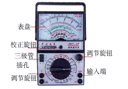
Figure 13-1 Diagram of the structure of a pointer multimeter
Dial: It consists of a high sensitivity magneto-electric ammeter and a dial. Magnetoelectric ammeter consists of permanent magnet, coil, hairspring, needle and so on, the full bias current is generally in the range of 40~100 μA. The hairspring plays the role of guiding the current and acting as a spring. When current flows into the coil through the spring, the coil generates torque under the action of magnetic field, overcoming the resistance of the spring and driving the meter needle to rotate. When the electromagnetic torque balances with the reaction force of the spring, the needle stops rotating.
Illustration of the four scale bars of the dial (from top to bottom):
- 🔹 (1) The first scale is the resistance scale;
- 🔹 (2) The second scale is used to measure AC voltage, DC voltage, and DC current;
- 🔹 (3) The third scale is used to measure voltages up to 10V;
- 🔹 (4) The fourth scale is used to measure the gain of the amplifier.
The measurement circuit is made up of resistors, diodes, etc. connected in series and parallel. The measurement circuit is the centerpiece of the multimeter, which converts different amounts of electricity into current.
Most multimeters use a multi-knife, multi-throw changeover switch in conjunction with the measurement mechanism to realize multi-function, multi-range conversion, and some multimeters use two changeover switches.
(iii) The use of pointer multimeters
(1) Meter pen insertion:Insert the red pen into the “+” jack and the black pen into the “-” jack.
(2) Zeroing:
① Mechanical zeroing:Lay the meter flat and adjust the calibration knob under the dial to align the pointer with the voltage/current zero position.
② Zeroing by Ohm's Law:Before measuring the resistance, short the red and black pens and adjust the ohm zero knob.Adjustments are required for each gear change.
(3) Function selection:Select the appropriate functional gear according to the object to be measured.
(4) Principles of range selection:The range must be greater than the measurement and should be closest to the measurement. Generally make the meter needle point at 1/2 to 2/3 Position. If the value is uncertain, it should first be determined using theMaximum rangeMeasurement.
(iv) Precautions for Pointer Multimeter
Second, digital multimeter (DT-830 type as an example)
Digital multimeters have the advantages of high measurement accuracy, intuitive display, full functionality, reliability, compactness, light weight and ease of operation.
(i) Structure and function
The DT-830 digital multimeter, shown in Figure 13-2, includes an LCD liquid crystal display, power switch, range selector switch, and pen socket.
● Display:Maximum value 1999. automatic display of polarity (“-” for negative polarity). Over-range display “1” or “-1”.
● Power switch:Set to the “OFF” position when measurement is complete. A 9V laminated battery is used.
● Jack specification:Insert “COM” with the black pen and “V-Ω”, “mA” or “10 A” with the red pen, depending on the type.
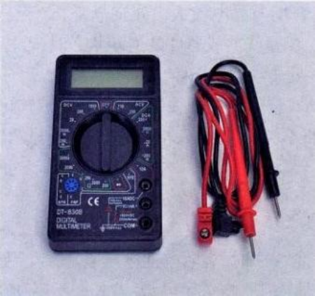
Figure 13-2 DT-830 Digital Multimeter
(ii) the use of digital multimeter
| Measurement Objects | Operating Points |
|---|---|
| AC and DC Voltage | Insert V-Ω and COM and connect the circuit. DC need to pay attention to the high potential end, range overflow to adjust the high grade. |
| AC and DC current | Insert mA (>200mA to 10A) and COM, series circuit. Note the polarity. |
| resistive | No zeroing required. Insert V-Ω and COM to measure across (not electrically charged). 200MΩ range minus offset. |
| Diode/On-Off | Forward voltage drop (silicon 500-800mV), reverse “1”. Resistance <30Ω Beep. |
| Transistor hFE | Set the range to hFE. Insert the pins into the appropriate EBC jacks by NPN/PNP type. |
(iii) Precautions for digital multimeters
● Battery alarm: Replace when “LOBAT” or “←” is displayed.
● Environmental requirements: 0~40℃, humidity below 80%. Direct sunlight or high temperature and humidity are strictly prohibited.
Third, the correct use of multimeter measurement of AC and DC voltage, current
(i) Voltage measurement
1. Uses:Determine power status and polarity; look for wiring faults.
2. Methodology:① Select gear. ② parallel measurement. ③ DC red positive and black negative (can be checked by touching method). Match the range (380V choose 500V stop, 220V choose 250V stop).
(ii) Measurement of current
1. Uses:Verify that equipment is working as expected; troubleshooting.
2. Methodology:① Black plug COM, Red plug mA or 10A. Series Access Circuit③ Be sure to insert the red pen back into the V-Ω jack after AC measurement. ③ Be sure to insert the red pen back into the V-Ω jack after AC measurement.
(iii) Precautions when using a multimeter to measure voltage and current
- (1) Topological Connections:Measurement of voltage must be connected in parallel, measurement of current must be connected in series, violators will destroy the meter.
- (2) Gear checking:It is strictly prohibited to measure AC in DC block or DC in AC block.
- (3) Range estimation:Start in a large gear and reduce the range to improve accuracy.
- (4) Reset homing:After the measurement is completed, the red pen must be put back into the “V-Ω” jack, and the change-over switch is placed in the AC high-voltage position.












 Chinese
 English
 Korean
 Japanese
 Thai
Thai Arabic
 Spanish
 Russian
 Vietnamese
 Indonesian

