

Inverter main parameter setting and panel operation practice
I. BOP Operation Interface and Functions
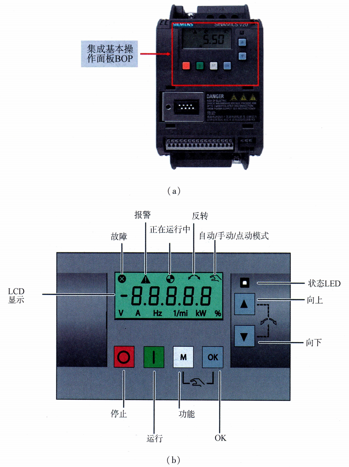
Figure 20-3 BOP Operation Interface
● Button Function:(See Table 20-1 Button Menu for details.)
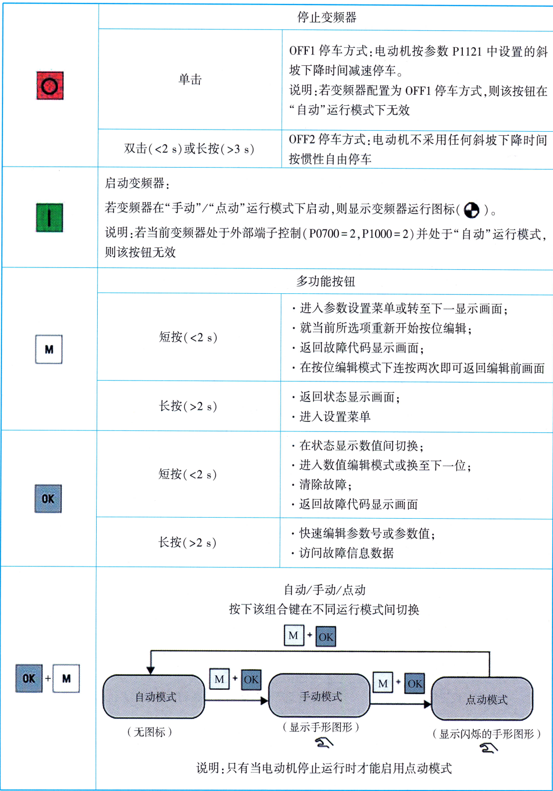
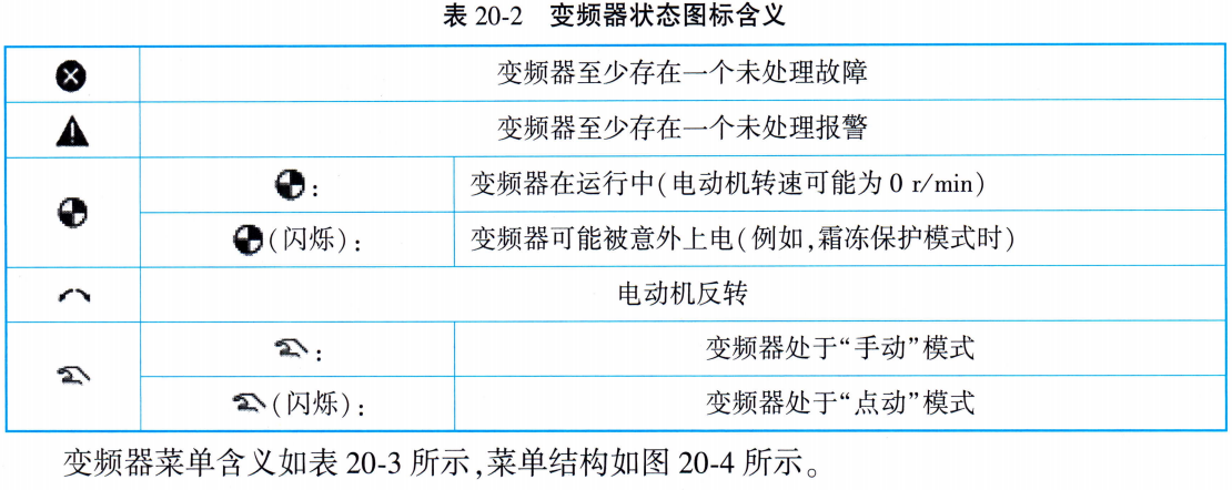
Table 20-1 Button Functions
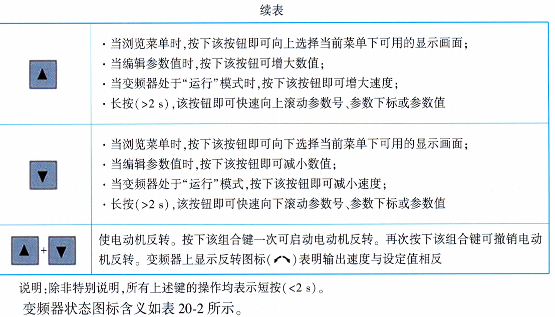
● Status Icon:(For details, see Table 20-2 Meaning of Inverter Status Icons)
 ● Menu Meaning:(For details, see Table 20-3 Inverter Menu Meaning)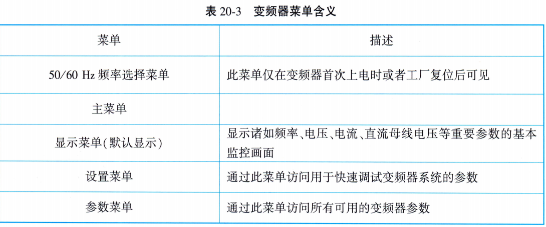
Inverter menu structure and monitoring
The display menu can display key parameters such as frequency, voltage, current, etc., thus realizing the basic monitoring of the inverter. The operation process of inverter parameter view is shown in Figure 20-5.
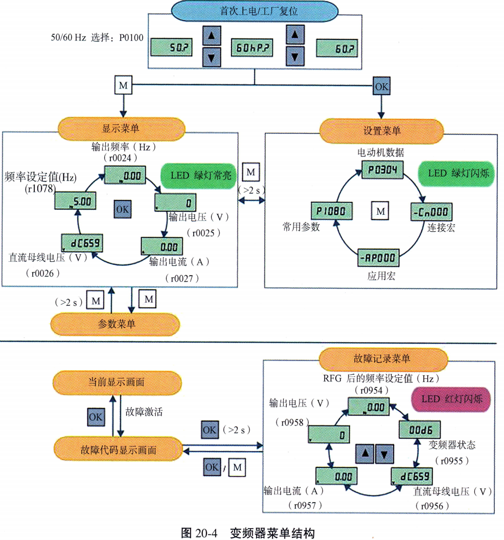
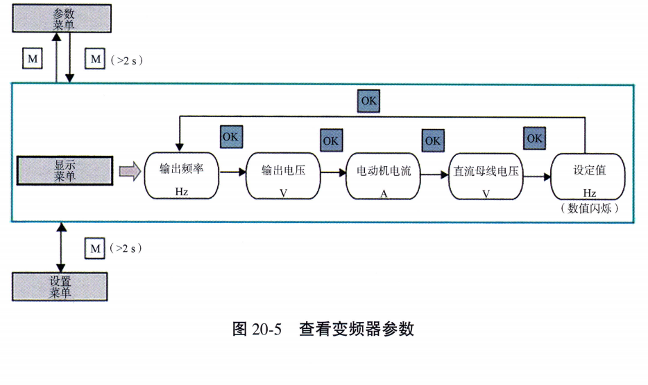
Figure 20-4 Inverter Menu Structure | Figure 20-5 Viewing Inverter Parameters
II. Parameter editing
● Parameter Type:(See Table 20-4 Parameter Type Table for details)
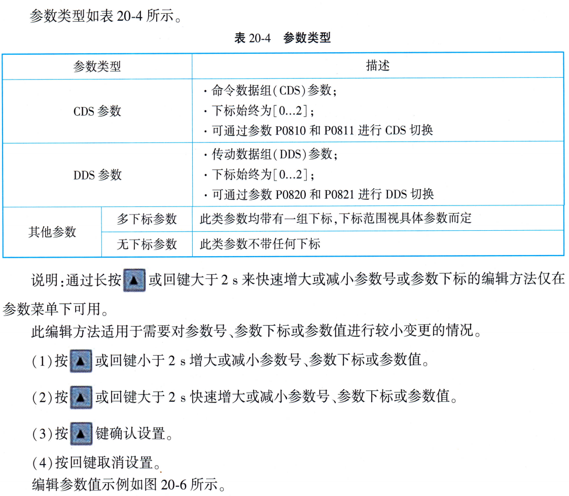
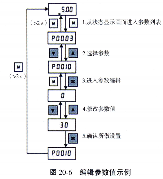
Figure 20-6 Example of Editing Parameter Values
LED Status Indication Priority
The SINAMICS V20 has only one LED status indicator, which can display orange, green or red. If more than one status exists for the frequency converter at the same time, the LED indicators are displayed in the following priority order:Parameter Clone > Debug Mode > Fault Occurrence > Ready (no faults). For example, if a fault occurs in debug mode, the LED flashes green at 0.5 Hz.
- (1) Check that all cables are properly connected and that all relevant safety precautions have been taken.
- (2) Make sure that the motor and inverter are configured to correspond to the correct supply voltage.
- (3) Tighten all screws to the specified tightening torque.
III. Parameterization during practice
(i) Setting the power frequency (50/60 Hz)
The 50/60 Hz selection menu is only visible when the inverter is first turned on or after a factory reset (P0970). The user can select the frequency via BOP or exit this menu directly without making a selection. The frequency can also be selected by setting the P0100 The motor rated frequency is selected by the value of [kW] or [hp] (see Table 20-8 for details). Determine the power value expressed in [kW] or [hp] by this setting.
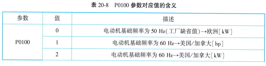
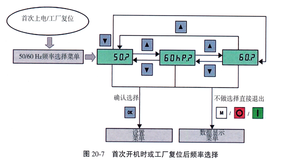 Figure 20-7 Frequency Selection at First Power-Up or After Factory Reset
(ii) Setting motor data and common parameters
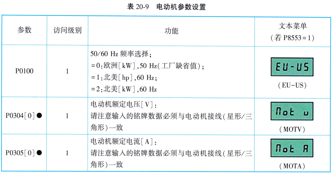
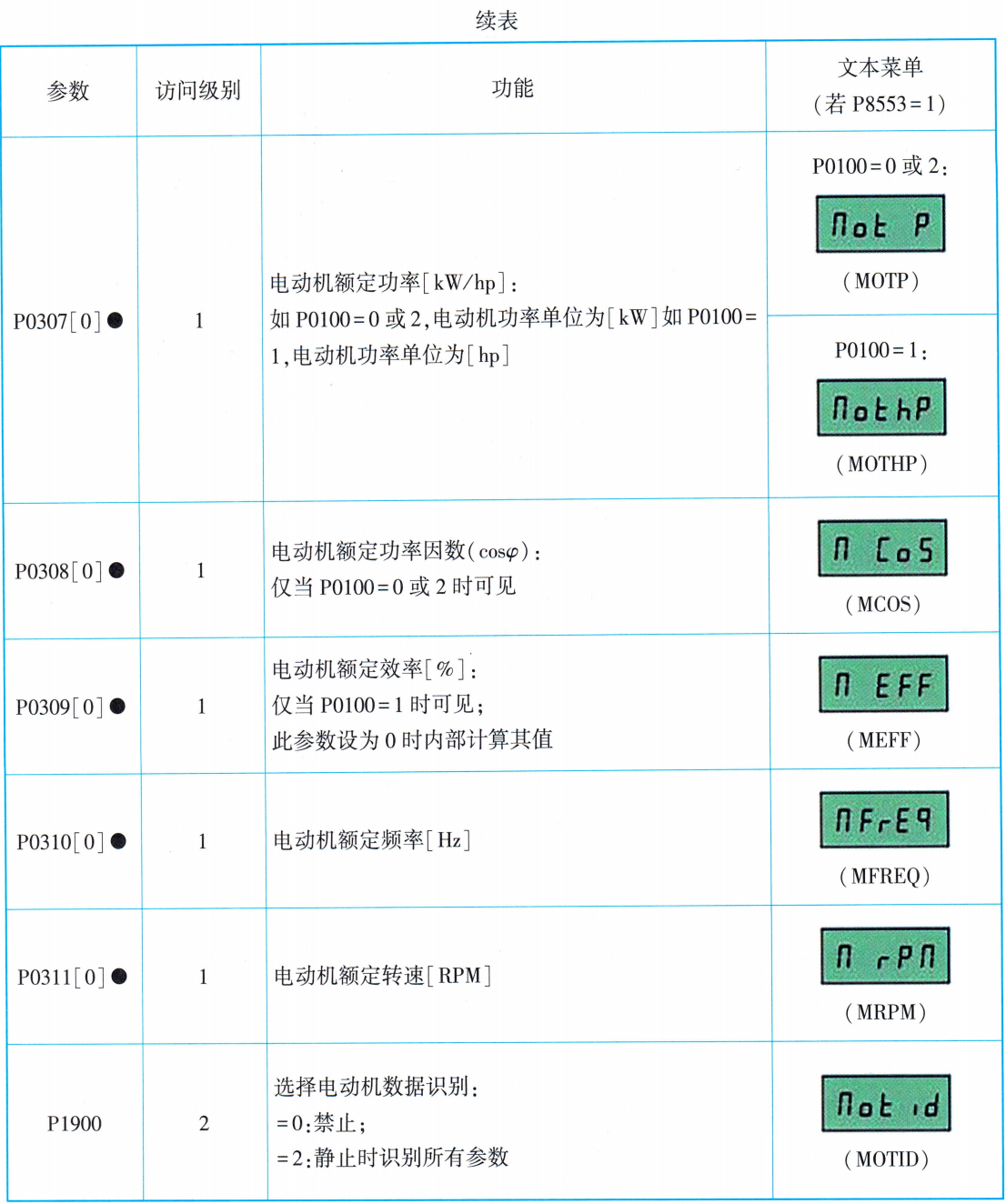
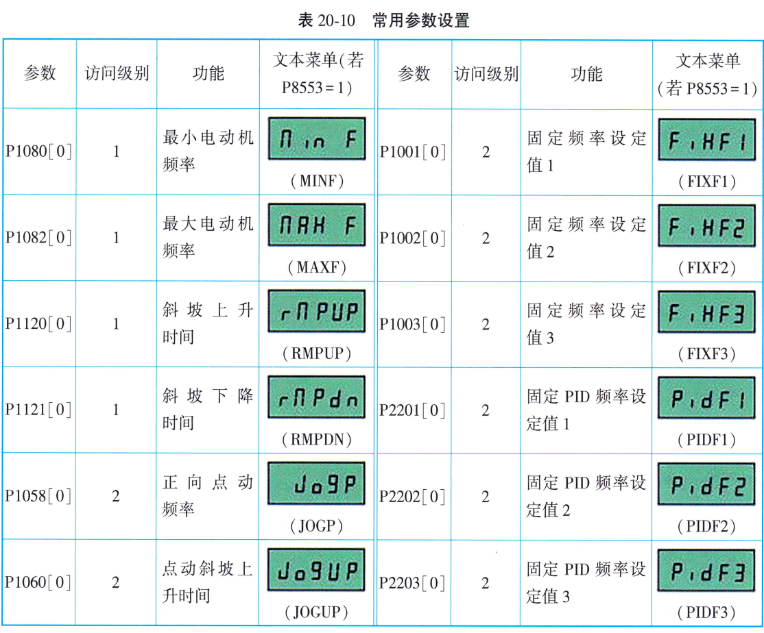
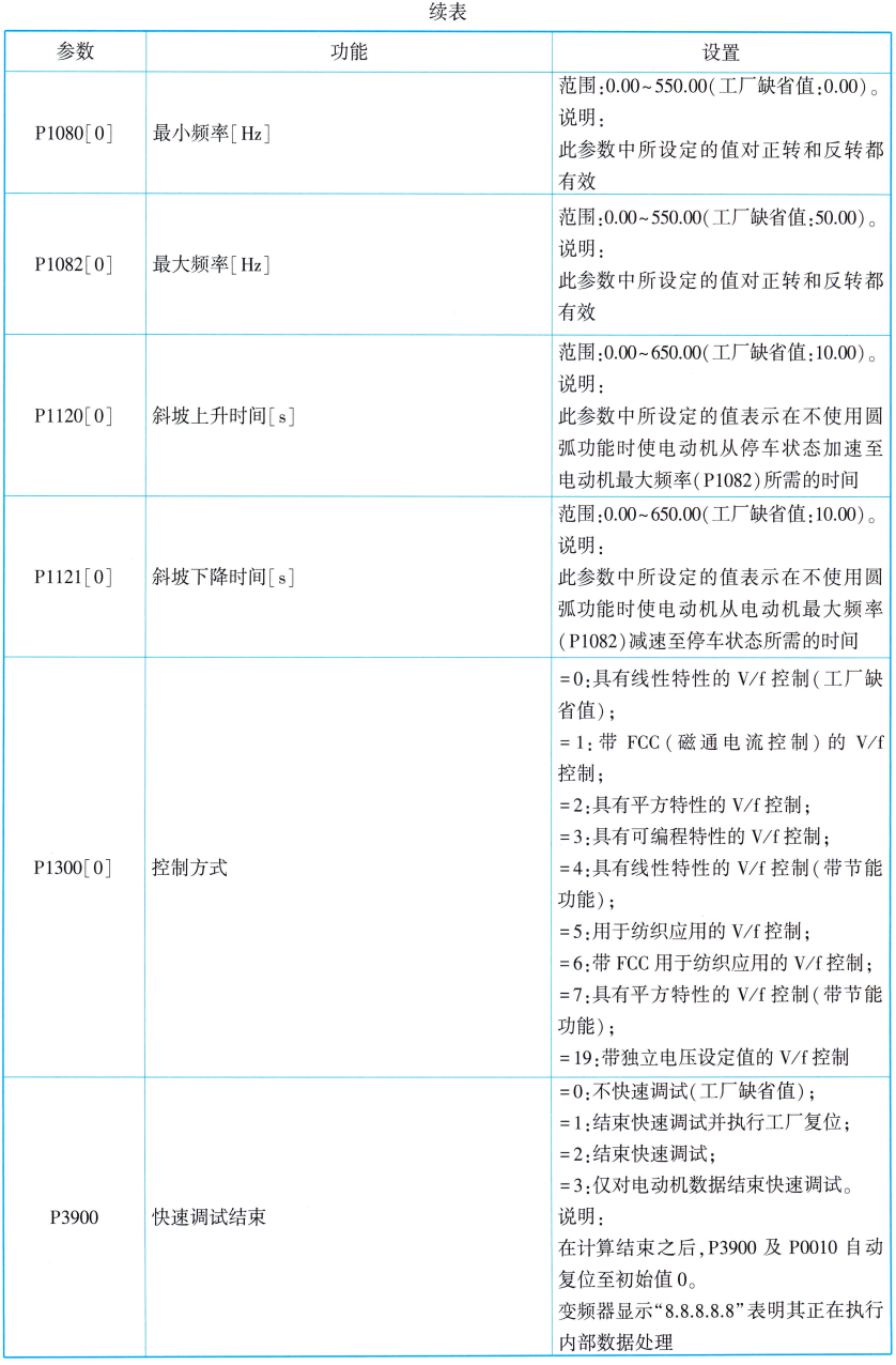
The user sets the motor nameplate data through the motor parameters in Table 20-9. If the parameter P8553 Setting 1, this menu displays text instead of a parameter number. Refer to Table 20-10 for common parameter settings.
 (iv) Rapid commissioning
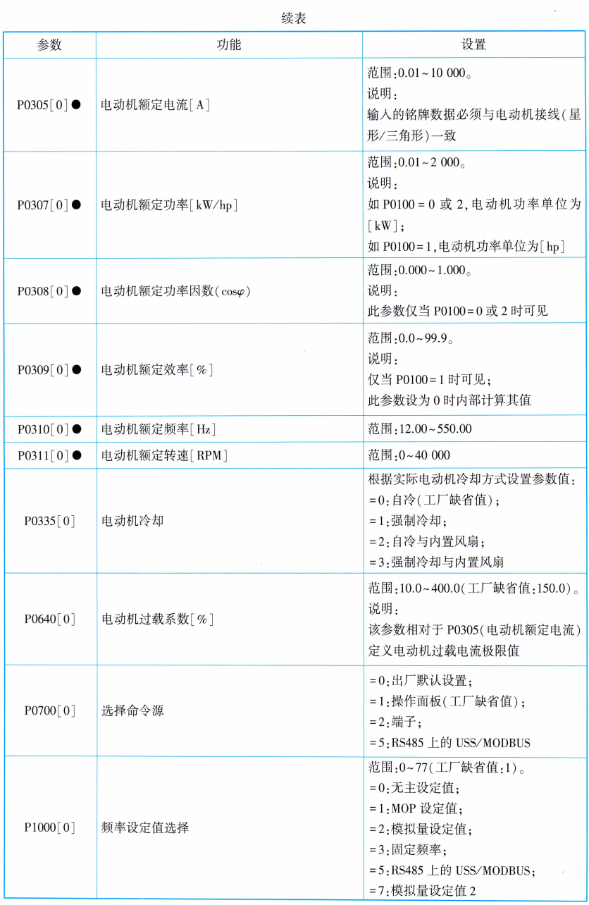
In addition to the setup menu, users can also perform quick debugging of the inverter through the parameter menu (see Table 20-11 for details).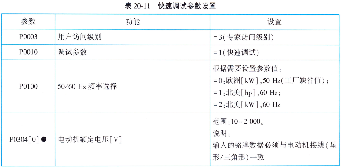

V. Debugging of other functions
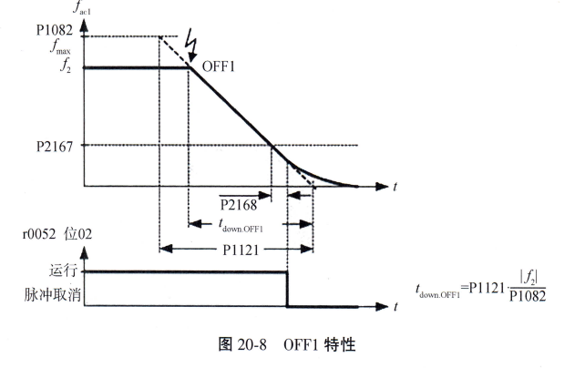
1. Parking mode selection (OFF1, OFF2, OFF3)
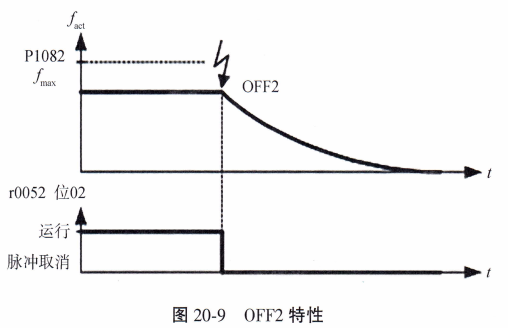
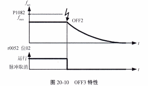
Note:The inverter will be in the ON disabled state after the OFF2/OFF3 command. At this time, it is necessary to give the ON command with signal changing from low level → high level to start the motor again. Priority order:0FF2 (highest level) → OFF3 → OFF1。
Use the ramp down time defined by P1121. The pulse is canceled when the output frequency drops below P2167 and the P2168 time ends.
Cancel the inverter pulse immediately. The motor stops freely by inertia and not in a controlled manner. Low level active.
Use its unique ramp down time P1135. which has the same braking characteristics as OFF1 but usually descends more steeply.
2. Pointing mode (JOG)
Press the “Run” button to rotate at the preset frequency (P1058) and release to stop. Application Scenario:
(1) Check motor and inverter functions after commissioning;
(2) To bring the load to a specific position;
(3) Rotate the motor after program interruption.
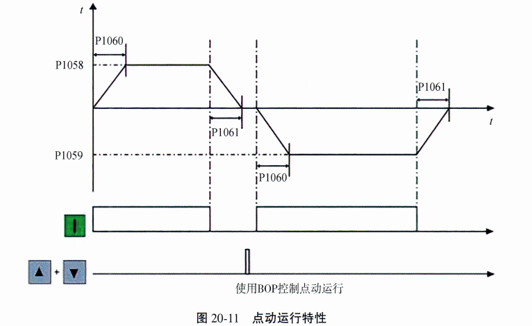
Figure 20-11 Pointing Operation Characteristics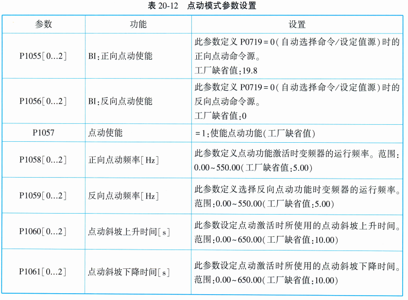
VI. Common Fault Codes of Inverter
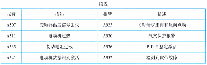
Key Function Description: Press OK key to view the current fault list. Press and hold OK (>2s) to view the inverter status at the time of the fault. The fault icon disappears when the fault is cleared/answered. (See Table 20-13 Fault Code List and Table 20-14 Alarm Code List for details).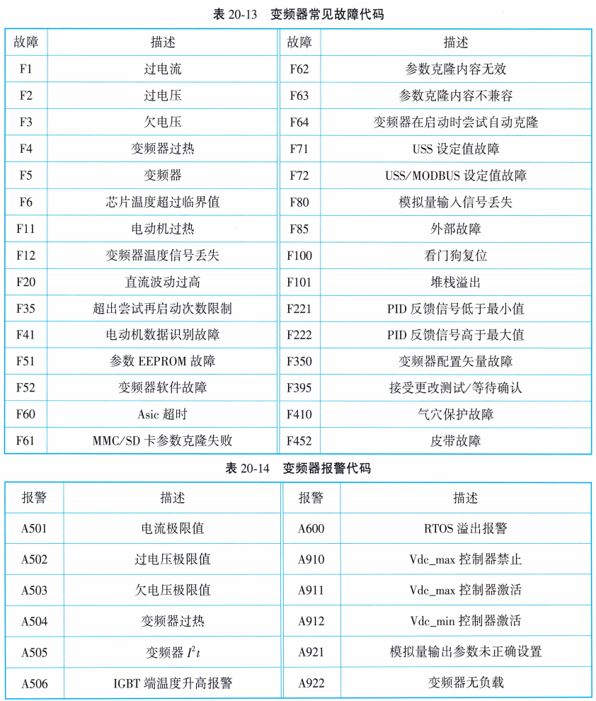











 Chinese
  English
  Korean
  Japanese
  Thai
Thai  Arabic
  Spanish
  Russian
  Vietnamese
  Indonesian

