

Contactor common faults, disassembly and repair practice
Contactor is the use of electromagnetic suction principle, frequently connect and cut off the high-current circuit (i.e., the main circuit) switching appliances, with a large control capacity, can be operated over long distances, can realize the characteristics of the interlocking control, and has a loss of voltage and undervoltage protection, is widely used in automatic control circuits. Its main control object is the motor, can also be used to control other electrical loads. Contactor according to the type of control current can be divided into AC contactor and DC contactor, the two types of contactor in the contact system, electromagnetic mechanism, arc extinguishing device and other aspects are different.
I. Structure and working principle of AC contactor
The AC contactor (shown in Figure 19-4) is mainly composed of an electromagnetic mechanism, a contact system, an arc extinguishing device, and other components. The electromagnetic mechanism is mainly composed of a coil, a static iron core and a moving iron core. The contact system consists of main contacts and auxiliary contacts. The main contacts are connected in series in the main circuit, the general contactor has three pairs of normally open main contacts; auxiliary contacts can be divided into normally open auxiliary contacts and normally closed auxiliary contacts, used to control the circuit. Arc extinguishing device used to quickly cut off the arc when needed to avoid burning the main contacts. Insulated housing and accessories often include a variety of springs, drive mechanism, terminal, etc..
How it works:After the coil is energized, magnetic flux and electromagnetic suction are generated in the iron core. This electromagnetic suction force overcomes the spring counterforce to make the movable iron core suction, driving the contact mechanism action, normally closed contacts open, normally open contacts closed. When the coil is de-energized or the voltage at both ends of the coil is significantly reduced, the electromagnetic suction force is smaller than the spring counterforce, which makes the moving iron core release, and the contact mechanism is reset, and the normally open contact is opened and the normally closed contact is closed.
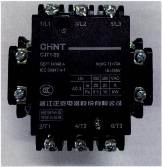 Figure 19-4 AC Contactor Outline Drawing
II. Common faults and repair of contactors
Table 19-1 Common Faults and Troubleshooting Methods for Contactors
| common trouble | Possible causes | Methods of elimination |
|
Cannot be closed when energized | (1) Broken or burnt coil; (2) Moving iron core or mechanical part stuck; (3) Rusted or crooked spindles; (4) Insufficient power supply capacity of the operating circuit; (5) Excessive spring pressure | (1) Repair or replace the coil; (2) Adjust the position of the parts to eliminate jamming; (3) Remove rust and grease, or replace parts; (4) Increase power supply capacity; (5) Adjusting the spring pressure |
| Moving iron core after energizing Can't get it all the way in. | (1) Power supply voltage is too low; (2) Excessive pressure on contact spring and release spring; (3) Contact overtravel is too large | (1) Adjust the power supply voltage; (2) Adjust the spring pressure or replace the spring; (3) Adjustment of contact overtravel |
|
Excessive noise or vibration of solenoid | (1) Power supply voltage is too low; (2) Excessive spring pressure; (3) Dirt or excessive wear and unevenness on the pole surface of the iron core; (4) Broken short circuit ring; (5) Loose core clamping bolts, core skewed or mechanically jammed | (1) Adjust the power supply voltage; (2) Adjust the spring pressure; (3) Remove dirt, repair pole surface or replace core; (4) Replace the short circuit ring; (5) Tighten bolts to eliminate mechanical problems |
|
Slow contactor action | (1) Excessive clearance between the moving and static iron cores; (2) Excessive pressure on the spring; (3) Insufficient coil voltage; (4) Incorrect mounting position | (1) Adjust the mechanical part to reduce the clearance; (2) Adjust the spring pressure; (3) Adjust the coil voltage; (4) Reinstallation |
|
Contactor does not release after power failure | (1) Contact spring pressure is too low; (2) The moving iron core or mechanical parts are stuck; (3) Excessive residual magnetism of the iron core; (4) The contacts are fusion welded together; (5) Oil or dust on the pole surface of the iron core | (1) Adjust the spring pressure or replace the spring; (2) Adjust the position of the parts to eliminate jamming; (3) Demagnetize or replace the iron core; (4) Repair or replace contacts; (5) Clean the core pole surface |
|
Overheated or burnt coils | (1) Excessive pressure on the spring; (2) The rated voltage, frequency, or duration of energization of the coil does not correspond to the operating conditions; (3) Excessive frequency of operation; (4) Coil turn-to-turn short circuit; (5) The moving part is stuck; (6) High ambient temperature; (7) The air is humid or contains corrosive gases; (8) Uneven pole surface of AC iron core | (1) Adjust the spring pressure; (2) Replace the coil; (3) Replace the contactor; (4) Replace the coil; (5) Rule out jamming; (6) Change the installation position or take cooling measures; (7) Take measures against moisture and corrosion; (8) Clear the pole surface or swap the iron core |
| Contacts overheated or burned | (1) Contact spring pressure is too low; (2) The contact surface has oil or the surface is uneven; (3) The overtravel of the contact is too small; (4) Insufficient breaking capacity of the contacts; (5) High ambient temperature or poor heat dissipation | (1) Adjust the spring pressure; (2) Clean the contact surface; (3) Adjust over-travel or replace contacts; (4) Replace the contactor; (5) Contactors used at reduced capacity |
|
Contacts are fused together | (1) Contact spring pressure is too low; (2) Insufficient contact breaking capacity; (3) Excessive number of contact openings; (4) Metal particles protruding or foreign matter on the contact surface; (5) Load side short circuit | (1) Adjust the spring pressure; (2) Replace the contactor; (3) Replace the contacts; (4) Clean the contact surface; (5) Troubleshoot short circuit and replace contacts |
|
phase-to-phase short circuit | (1) Unreliable interlocking of reversible contactors, resulting in two contactors being put into operation at the same time and causing a short circuit between phases; (2) The contactor moves too fast and an arc short circuit occurs; (3) Dust or oil deteriorates insulation; (4) Damaged parts | (1) Check electrical and mechanical interlocks; (2) Replace the contactor with a longer action time; (3) Frequent cleaning to maintain cleanliness; (4) Replacement of damaged parts |
III. Testing of AC contactors
1. Visual inspection
Check that the AC contactor is complete and intact, that there is no cosmetic damage, and that the terminals and screws are intact.
2. Detection of main contacts
Set the multimeter tobeeping soundThe two pens are connected to the main contacts on both sides, no sound; press the moving iron core, if there is a beeping sound indicates that the work is normal, otherwise damaged.
3. Detection of auxiliary contacts
Beeping block connected to both ends, press the button to test. Judge whether the normally open/closed contact action logic is correct (beeping/not beeping), otherwise it is damaged.
4. Testing of Coils
Set the multimeter to R x 1k resistorThe coil is connected to both ends of the coil, and the actual resistance value of the coil is measured to see if it meets the requirements.
IV. Disassembly and installation of AC contactors
(i) Contactor disassembly procedure
- 1. Remove the interrupter:Remove the upper fastening screws and remove the arc extinguisher.
- 2. Remove the main contacts:Tighten the locating spring clip and remove the movable contact bridge and pressure spring tab. It must be removed by turning it 45° sideways and unscrewing the static contact screw.
- 3. Remove the static contact of the auxiliary contact:Loosen the terminal screw and remove the auxiliary normally open static contact.
- 4. Remove the bottom cover:With contactor inverted, loosen bottom cover screws. Gumwood cover plate must be pressed down to prevent the buffer spring from popping out.
- 5. Remove the static core:Remove the static core and cushion insulating paper sheet, remove the bracket and cushion spring.
- 6. Remove the solenoid:Remove the coil by pulling out the coil terminal spring clip.
- 7. Remove armature and bracket:Remove the reaction spring, armature and bracket, remove the movable iron core locating pin, movable iron core and cushion insulating paper sheet. This is the end of disassembly.
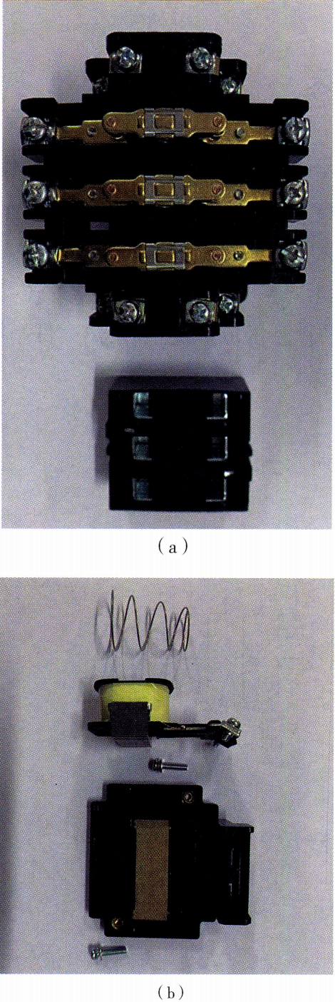 Figure 19-5 Contactor Removal
(ii) Repair and assembly of contactors
The main components of the contactor to be repaired or replaced are the movable and static main contacts and the solenoid coil. Assembly after repair can be carried out in steps opposite to disassembly.
(iii) Functional testing of contactors
Power failure test:Select the multimeter resistance block range to check if the coil is good; use the buzzer block to check the main and auxiliary contacts. Press the top of the insulated linkage with your hand during the test. Check whether the moving part is flexible. Use megohmmeter to check the insulation resistance between each main contact and to the shell.
Power on test:According to the nameplate data to access the coil voltage, check the main contact, auxiliary contact is good.
(iv) Disassembly and assembly precautions
- (1) During disassembly, containers for parts should be available to avoid loss. Parts should be stored neatly in order.
- (2) Hard prying is not permitted during disassembly or assembly to avoid damage to the appliance. When assembling the auxiliary static contacts, prevent jamming the movable contacts.
- (3) During the energized test, the contactor should be fixed on the control board and supervised to ensure the safety of electricity.
- (4) When adjusting contact pressure, be careful not to damage the main contacts of the contactor.












 Chinese
 English
 Korean
 Japanese
 Thai
Thai Arabic
 Spanish
 Russian
 Vietnamese
 Indonesian

