

Basic radar operation
Practical Procedures Manual for the Marine Electronics and Electrical Technician Program
Electronics and electrical technicians must be proficient in basic radar control operations, including checking external sensors, performing basic adjustments to radar images, and turning the radar on and off.
I. Basic Radar Controls
Radar control buttons can be divided into six major categories: power control, image quality control, clutter suppression, auxiliary control, observation tools, and display mode control. With the exception of power control, most radars can be operated using on-screen soft-panel menus and hard-panel control buttons. The Furuno FAR-2827 control panel is shown in Figure 1-2-1.
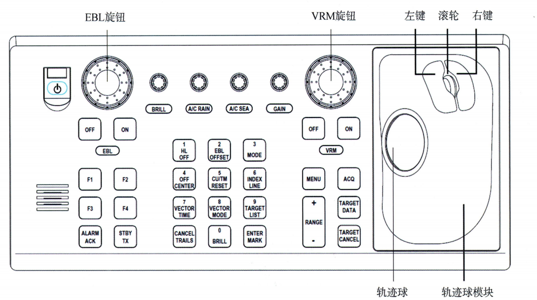 Figure 1-2-1 Furuno FAR-2827 Control Panel
(I) Sensor Data Verification and Device Connection
1. Sensor Data Check
Essential sensors for radar include pointing devices, speed-and-distance measurement devices, electronic positioning systems, and automatic identification systems. If the radar fails to receive signals from these sensors, an alarm will be triggered; see Table 1-1-3. Immediately after turning on the radar, verify that sensor data is being transmitted correctly to the radar. The data input display on the radar monitor is shown in Figure 1-2-2.
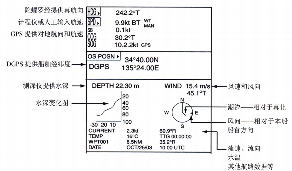 Figure 1-2-2: Data Acquisition Display on the Radar Monitor
2. Connecting Sensor Devices
The connection between the radar system and external sensors is typically located on the radar display unit. When the alarm window on the radar display shows a sensor connection fault, open the rear cover of the radar display unit—the interface is shown in Figure 1-2-3—and check whether the connector between the radar and the sensor is loose.
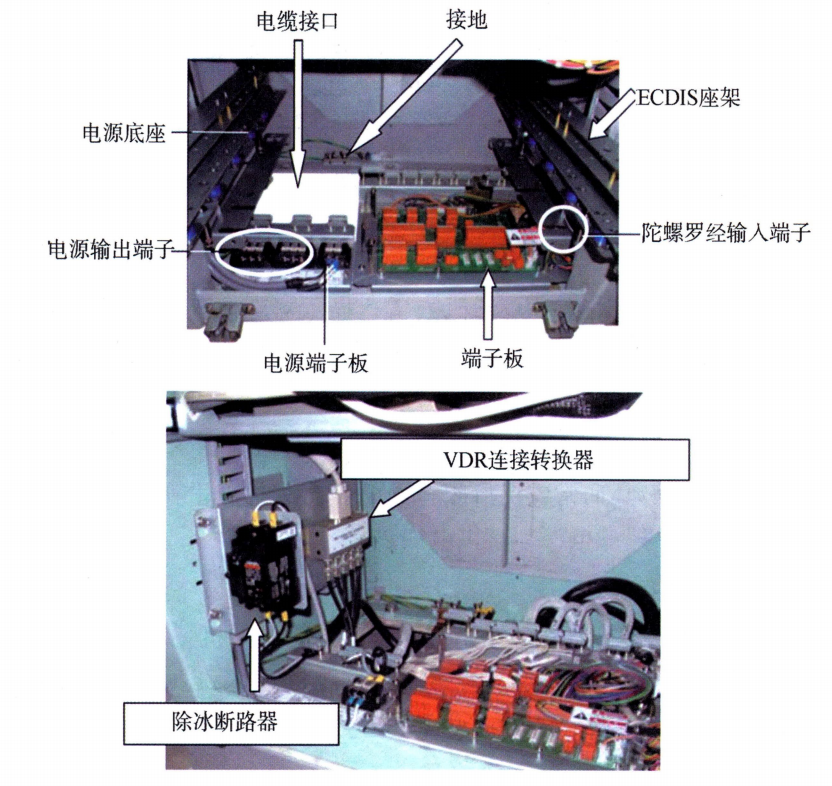 Figure 1-2-3 Radar Display Unit Interface
The terminal circuit board shown in Figure 1-2-3 features numerous interfaces for radar sensors, as shown in Figure 1-2-4.
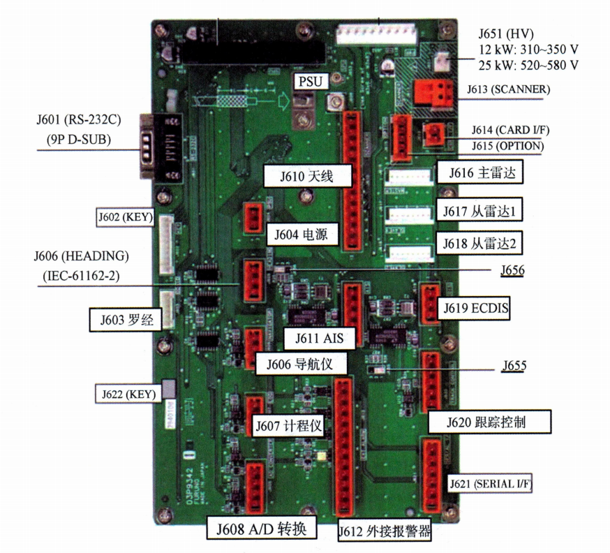 Figure 1-2-4: Terminal Board Interface Layout
(2) Power Switch
The radar power supply control components include the main radar power switch, the radar display power switch, and the antenna safety switch. The radar is designed for 24-hour, all-weather operation; except for the magnetron (a component with a limited service life), frequent operation of the radar power switch should be avoided during navigation.
1. Marine Electrical Switches: All radars are equipped with dedicated power switches, which should normally remain closed and energized. Some radars have dehumidification heating resistors installed in each enclosure; when the radar is not in operation, these are powered by the ship’s electrical system to provide heat.
2. Power Switch: After turning on the power switch (Power) on the radar display control panel, power is supplied to all parts of the radar except for the transmitter’s ultra-high-voltage power supply. After 3 minutes, the time-delay relay contacts close, and the transmitter enters a standby state; at this point, the screen displays “Standby.”
3. Transmit Switch: The transmit switch (TX or Transmit) is used to control the operating status of the radar transmitter. When the radar is in standby mode, activating this switch starts the radar; activating it again returns the radar to standby mode. When using the transmit switch, please note that during work breaks when the radar is not in use, it should be set to the standby state to extend the service life of the magnetron.
4. Antenna Safety Switch: Many radars are equipped with a safety switch on the antenna base. When technicians perform maintenance on the equipment, turning off this switch ensures their safety.
(3) Image Quality Control Knob
The main controls for adjusting radar image quality include screen brightness (contrast), gain, tuning, and clutter suppression; auxiliary controls include echo expansion and echo averaging. The main controls for adjusting Furuno radar images are shown in Figure 1-2-5. Electronics and electrical technicians must master the use of the main image adjustment controls through hands-on practice and become familiar with the screen response states of the corresponding controls.
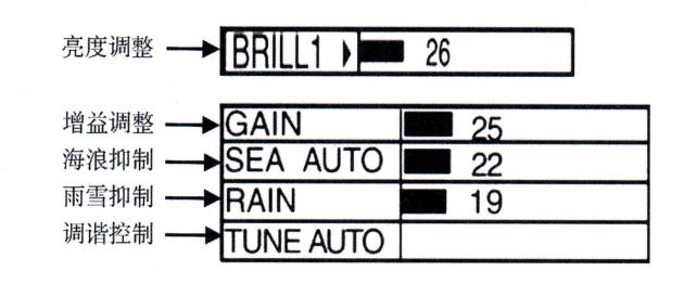 Figure 1-2-5: Main Controls for Adjusting Furuno Radar Images
1. Screen brightness: The screen brightness should be adjusted appropriately to match the ambient light.
2. Gain: The gain control knob is used to adjust the amplification level of the intermediate-frequency amplifier in the radar receiver. Adjusting the gain control changes the intensity of the echoes and noise in the radar image; the initial optimal setting should be such that noise spots are just barely visible.
3. Tuning: The tuning knob is used to adjust the local oscillator output frequency, ensuring that the frequency converter’s output remains stable at the rated intermediate frequency. The radar is equipped with a tuning indicator; when adjusting, set the tuning indicator to its maximum, then fine-tune the knob to produce a full and clear echo. If the tuning is not optimal, symptoms such as blurred echo edges, unsaturated brightness, sparse video, and poor contrast may occur.
4. Clutter Suppression: The clutter suppression controls on modern radars include the following functions: sea clutter suppression (SEA/ or STC) and automatic sea clutter suppression (AUTO-SEA), rain and snow suppression (RAIN/ or FTC) and automatic rain and snow suppression (AUTO-RAIN), as well as in-band interference suppression (IR), among others.
(1) Wave Suppression and Automatic Wave Suppression: The level of wave clutter suppression should be adjusted appropriately by setting the STC according to observation requirements to ensure, as much as possible, the detection of weak echoes in waves or clear observation of targets. Do not set the STC too high, as this may result in the loss of weak targets.
(2) Rain and Snow Suppression and Automatic Rain and Snow Suppression: Rain and snow suppression effectively suppresses interference from rain and snow while improving the range resolution of echoes. The adjustment criteria are similar to those for STC; the FTC should be adjusted appropriately based on actual precipitation conditions and observation requirements. Do not set the FTC too low, to avoid losing weak targets.
(3) Co-frequency interference suppression: Since co-frequency interference suppression employs scan-correlation detection technology—which performs correlation detection on two or more adjacent scan lines—it effectively suppresses weak targets with unstable echoes. It is typically used only when co-frequency interference severely affects radar observations.
(4) Observation Control Button
Observation controls are used to measure the target’s position and determine its movement. Controls directly used to determine the target’s position typically include the range (RANGE), fixed range ring (RR), variable range ring (VRM), electronic bearing line (EBL), and home line (HL), as shown in Figure 1-1-12. Electronics and electrical personnel should be able to accurately identify these scale markings and be familiar with their functions.
(1) Measurement range: The “Marine Radar Performance Standards” require that radars provide ranges of 0.25 n mile, 0.5 n mile, 0.75 n mile, 1.5 n mile, 3 n mile, 6 n mile, 12 n mile, and 24 n mile. Generally, radars provide additional ranges beyond the mandatory settings; a common minimum range is 0.125 n mile, while the maximum range can reach 96 n mile or 120 n mile. When the range is changed, various technical parameters of the radar transmitter and receiver are adjusted accordingly.
(2) Fixed-distance marker ring: RR provides a reference scale for measuring the range to a target; when used for navigation, the radar typically displays the RR, but its brightness should not be too high so as not to interfere with target observation. At ranges below 0.75 nautical miles, there are typically 3 or even 2 RRs; at ranges above 1.5 nautical miles, there are typically 6 RRs.
(3) Distance from the target ring: The radar provides at least two VRMs for accurately measuring the distance to a target. If the target is located beyond the radar’s horizon at sea and its leading edge cannot be detected, the trailing edge of the target’s echo should be measured.
(4) Electronic bearing lines: The radar shall provide at least two EBLs and shall support measurements relative to the heading and relative to true north. It shall be capable of measuring the bearing of any point target within the working display area, with a maximum system error of 1° at the display edge.
(5) Bow line: The bow line is a special marker line on the radar screen, provided by the vessel’s heading transmitter or gyrocompass, which is used to indicate the vessel’s heading.
II. Steps for Turning the Radar On and Off
(I) Preparations Before Starting Up
Preparations should be made before turning on the radar. First, ensure that there are no people or obstacles on the antenna. In particular, after heavy winds and rough seas, carefully check the area around the antenna for any loose rigging that could interfere with the antenna’s rotation. Before turning on the radar, also check that the important control knobs on the control panel are in the correct positions. Set all interference suppression controls and echo enhancement controls to their minimum (off) positions.
(2) Startup Procedure
(1) Turn on the radar power and wait 3–5 minutes for the magnetron to warm up.
(2) Once the radar enters the “Standby” mode, set the transmit switch to the “Transmit” position.
(3) Adjust the brightness control knob to match the screen brightness to the ambient lighting for easier viewing.
(4) Adjust the gain control knob until noise spots become visible.
(5) Adjust the tuning knob to first bring the tuning indicator to its maximum value, then fine-tune it to ensure the echo is full and clear; next, set the tuning mode to automatic tuning and verify that the echo quality is at least as good as the best result achieved with manual tuning.
(6) Activate various anti-jamming circuits and radar image quality control devices as needed.
Note: If the radar is restarted shortly after being turned off, the magnetron will still be in the warm-up state, which may shorten the warm-up time.
(3) Shutdown Procedure
(1) Return all anti-clutter controls to the off position.
(2) Turn off the radar power.
Note: If you change the radar settings before turning off the power, wait at least a few seconds before turning off the power to ensure that the changes are saved to flash memory.











 Chinese
  English
  Korean
  Japanese
  Thai
Thai  Arabic
  Spanish
  Russian
  Vietnamese
  Indonesian

