Heavy Load Query and Automatic Switching Operation for Critical Workloads
I. Overview of Heavy-Load Query Functionality
On modern vessels, high-power loads with individual units reaching hundreds or even thousands of kilowatts are increasingly common. Examples include propulsion systems, thrusters, large capstans, large fire pumps, and specialized power loads on engineering vessels, whose capacities can rival those of individual generator sets. To start such heavy loads, one must first verify whether the existing power reserve in the ship's power plant can meet the requirements for both starting and operating the heavy load. If the power reserve is insufficient to meet the starting and operating requirements of the heavy load, the standby unit must be started first, synchronized, and only after confirming sufficient power reserve is the heavy load permitted to connect to the grid. This is the heavy load inquiry function.
To enable the heavy-load inquiry function, the “Start” button on the high-power load start box sends a signal not to the control circuit within the control box, but to the automatic power station management system. The management system then determines whether to start the standby unit. Only when sufficient power reserves are available on the grid does the management system issue a start command for the high-power load, putting it into operation.
The start inquiry circuit is shown in Figure 2-9. A “start permit” contact is inserted in series with the original start circuit. This contact pair can be directly supplied by the automatic control system or extended via a relay. Considering that typical automatic control systems only output one contact pair, an extension relay K₂ is installed in the starter. The start button S₂ has two pairs of normally open contacts: one pair for starting and one pair for start inquiry. When the inquiry selector switch S₃ is set to the “Inquiry” position, pressing S₂ will not activate contactor K₁ because the K₂ coil is not energized. When the inquiry circuit is energized, a start inquiry signal is sent to the automatic control system. Upon receiving a valid start request, the corresponding output contact of the automatic control system closes. This energizes the K₂ coil, causing the indicator light to illuminate, signifying readiness for startup. Pressing the start button S₂ again energizes the K₁ coil, starting the motor. Simultaneously, the auxiliary normally closed contact of K₁ opens, disconnecting the inquiry circuit to prevent repeated requests during operation.
 II. Heavy-Load Query Function Demonstration
The demonstration process of heavy-load queries on the simulator is as follows:
(1) Status Setting 1: The power station is in automatic mode, operating with a single unit, approaching 60% load.
Press the heavy load inquiry button on the simulated load. When grid power reserve is insufficient, the yellow indicator flashes, indicating a need to wait for the power station to synchronize. Observe the unit's automatic start-up, automatic synchronization, and automatic load transfer. Subsequently, the yellow indicator extinguishes, the load is automatically engaged, and the green indicator illuminates. During this process, carefully observe the instantaneous changes in grid load during load engagement.
(2) State Setting 2: The power station is in automatic mode with dual units operating in parallel, each carrying less than 50% load.
Press the heavy load inquiry button on the simulated load. If the grid reserve power is sufficient, the load starts directly and the green indicator light illuminates.
III. Automatic Switching of Critical Loads
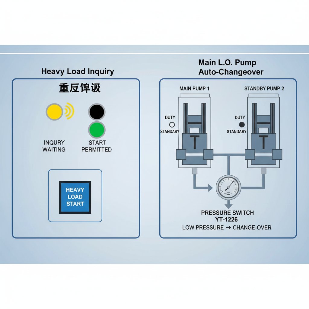
Critical onboard systems such as the main engine lubrication system and the main seawater system must ensure uninterrupted operation under corresponding working conditions. In addition to being equipped with two sets of power equipment, these systems should also feature automatic switching capabilities. This ensures that when one set of operating equipment fails, the other set automatically activates to meet the vessel's operational requirements. The following section illustrates this principle using the automatic switching of the main engine lubricating oil pump as an example.
1. System Composition and Workflow
The automatic switching system for ship main engine lubricating oil pumps primarily consists of two major components: the lubricating oil pump and the control assembly, as shown in Figure 2-10. A pressure switch must be installed in the pump pipeline, while the control assembly incorporates a PLC and general-purpose control electrical circuitry.
The automatic switching control circuit diagram for the lubricating oil pump primary and standby operation is shown in Figure 2-11. The operational sequence is as follows: Manually start Lubricating Oil Pump No. 1, while Lubricating Oil Pump No. 2 is set to automatic mode. Pump No. 1 serves as the primary pump, and Pump No. 2 functions as the standby pump. Only after the primary pump begins operation can the standby pump transition to standby status (at which point the standby pump is set to automatic mode).
Function 1: After the primary pump starts, the standby pump defaults to automatic mode. When the PLC detects the primary pump's operational signal, the standby pump indicates “Standby” output. If the pressure switch's low-pressure signal persists for 10 seconds, the standby pump activates while the primary pump stops (primary pump reports fault).
Function 2: When any pump is running and the busbar on the distribution panel loses power, the pump will resume its pre-power-loss state within 20 seconds of the next power-up (this function is unaffected by pressure switches or automatic mode).

 2. Pressure Switch Principle and Adjustment
The automatic switching of the main lubricating oil pump is typically triggered by a pressure switch.
The following explanation uses the YT-1226 pressure regulator as an example. Figure 2-12 shows the structural principle diagram of the YT-1226 pressure regulator. The measured input signal pressure P is connected to the measuring chamber. It is converted into a force signal via the bellows and acts on the comparison lever, generating a measuring torque. Additionally, the lever experiences a setpoint torque generated by the setpoint spring and a differential torque produced by the differential spring.
 When the input signal pressure P is at the lower limit value, the comparison lever remains in a horizontal position. At this point, the moving contact disengages from stationary contact 1 and closes with stationary contact 2. A certain clearance exists between the adjusting screw and the differential spring disc, preventing the differential spring from exerting force on the lever. As pressure P increases, the comparison lever rotates counterclockwise around its pivot point. This causes the lower frame of the reed switch to shift left via the lever arm, compressing the reed spring through the reed blade and storing elastic energy. Simultaneously, the gap between the adjusting screw and the differential spring disc gradually disappears. As the comparison lever continues to rotate, it must overcome not only the set torque but also the differential torque. Upon reaching a specific angle of rotation—indicating the measured pressure P has attained its upper limit—the reed blade aligns precisely with the reed plate. This allows the snap spring to release stored energy, rapidly propelling the reed plate away. Consequently, the moving contact disengages from stationary contact 2 and closes with stationary contact 1. When pressure P decreases, the comparison lever rotates clockwise around its pivot. Upon returning to the horizontal position, the reed blade aligns again with the reed spring. The snap-action spring then pushes the reed blade away, causing the moving contact to open from stationary contact 1 and close with stationary contact 2. When pressure P fluctuates between the upper and lower limits, the spring maintains its original state, meaning the regulator's output remains unchanged.
The spring setting adjusts the lower limit value of the pressure switch, denoted as P₁. The differential adjustment knob is used to set the pressure differential △P. The upper limit value Pa of the pressure switch equals the lower limit P₁ plus the differential △P, i.e., PH = P₁ + △P. Therefore, the upper limit value of the pressure switch is set by adjusting the differential.
The YT-1226 pressure switch has a set pointer indication range of P₁ = 0 to 0.2 MPa. The differential adjustment knob is marked with 10-division scales, corresponding to a differential range of ΔP = 0.07 to 0.25 MPa. The number of divisions X adjusted by the differential adjustment knob can be estimated using the following formula. However, due to the relatively low accuracy of the scale, experimental determination or on-site adjustment should be performed during actual use.


