Identification of the basic structure of a ship's generator main switch, Handle closing and opening operation
一 Recognize the shape and mechanism of the main switch
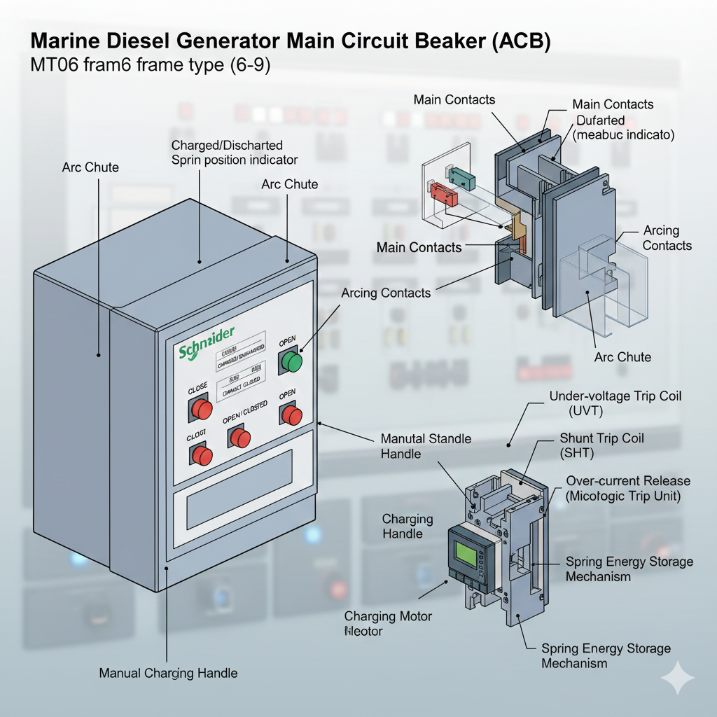
Recognize the shape of the frame type intelligent main switch (Schneider MT06) on the main switchboard of the automation simulator cabin, and recognize the closing and opening buttons, the closing and opening indicator plate, the energy storage indicator plate, and the relevant parameters of the electronic release device. Observe the shape of the main switch on the main switchboard of the power plant simulator, as shown in Figure 3-1.

Remove the three arc extinguishing covers of the DW95 main switch used for demonstration operation, observe the main contacts, auxiliary contacts, and the structure of the arc extinguishing covers, as shown in Figure 3-2.

Locate the three striker locations in the main switch, including the loss-of-voltage striker, the shunt striker, and the overcurrent striker, as shown in Figure 3 - 3. Observe the position of the spool in relation to the three strikers and the manual release button.

Identify the closing mechanism of the main switch, including the manual closing button, manual breaking button, closing solenoid, and energy storage spring. Observe the appearance of the IC striker, as shown in Figure 3 - 4, to understand the parameters that can be set for the IC striker.

II. Closing and breaking operations of main switches
1. Main switch closing and breaking conditions
In stand-alone operation, as long as the tripper is not in the state of disconnection (loss of voltage disconnecting coil does not operate, partial excitation disconnecting coil and overcurrent disconnecting coil do not operate), and the energy storage spring has stored energy, press the closing button to close the circuit. In parallel operation, in addition to the above conditions, it is also necessary to turn on the synchronization meter, and only when the conditions for parallel operation are met, can the closing button be pressed.
In stand-alone operation, first remove the load, so that the generator is in a no-load or light-load state, and then press the switch button to open the gate. In parallel operation, it is necessary to transfer the load first, and when the conditions for unlisting are met, the main switch can be released by pressing the release button.
2. DW95 main switch operation
Manually simulate the loss of voltage release device energized state (press the solenoid moving armature simulation energized suction), manually trigger the closing handle to close the gate, pay attention to the observation of the energy storage spring energy storage, release the process of closing the gate.
External test device, first energize the loss-of-voltage detent, then energize the closing coil, spring energy storage, closing coil de-energized, energy storage release closing.
In the closed state, press the manual trip button to trip the main switch, and observe the rotation of the striker shaft and the tripping action.
In the closed state, press the loss-of-voltage button to de-energize the loss-of-voltage disconnect and observe the tripping process.
In the closed state, press the shunt button to energize the shunt disconnector and observe the shunt process.
3. Operation of main switching test set (Schneider switch)
The energy storage setting switch is turned to manual, manually store and close the main switch and observe the process of closing the main switch.
The energy storage setup switch is turned to auto, a closing is performed, and the change in energy storage status is observed.
In the closed state, the main switch is tripped using the machine-side, remote control and loss-of-voltage settings, respectively, and the process of tripping the main switch is observed.


