Main Switch and Its Control Circuit Maintenance and Repair
I. Principle analysis of marine main switch control circuit protection function
以 DW98 Automatic Air Circuit Breaker For example. This model adopts a semiconductor detent as a protection device and is capable of realizing four protection functions: undervoltage delay, mega short-circuit instantaneous, short-circuit short-delay and overload long-delay.
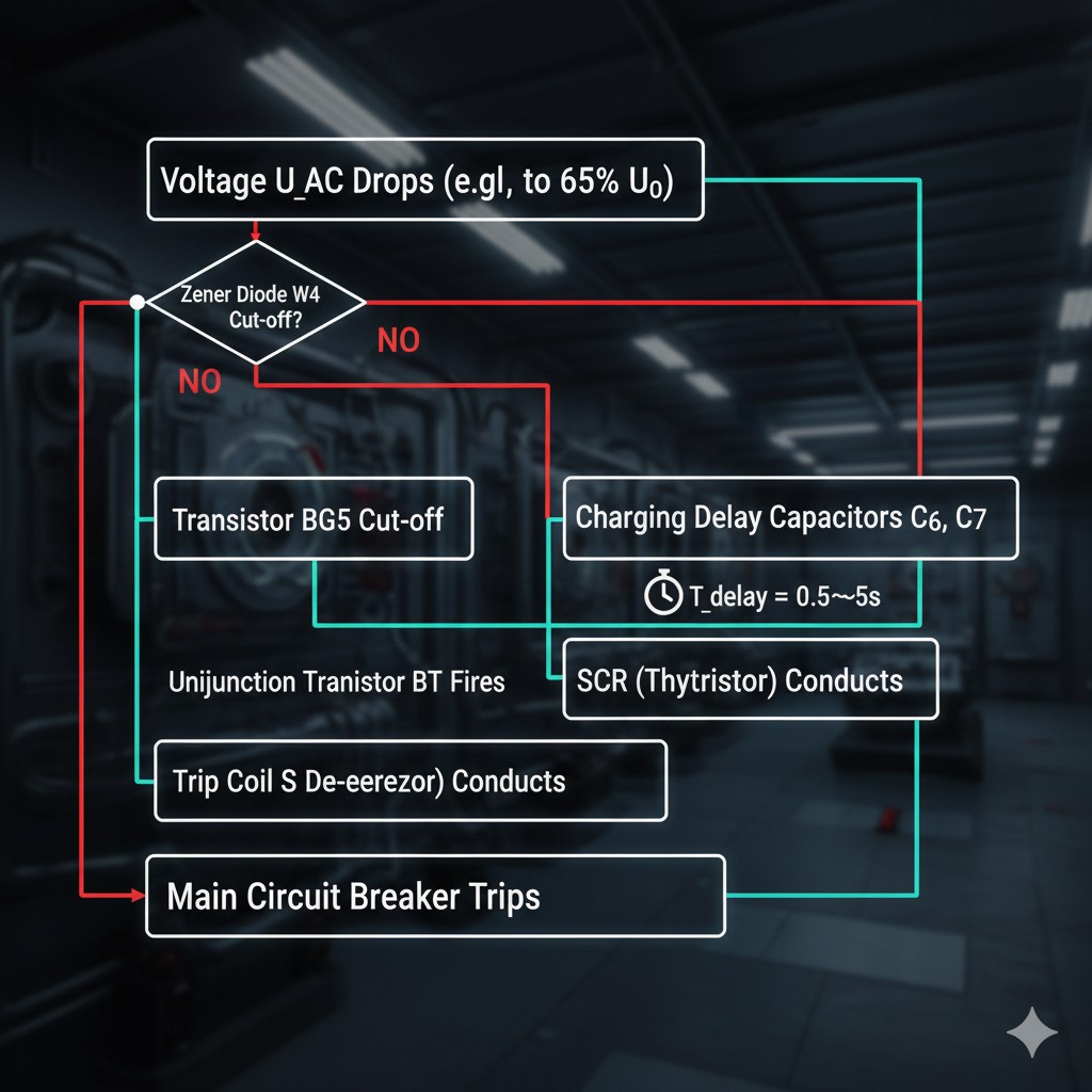
 1. Undervoltage delay trip protection
Power supply: The generator voltage is stepped down by transformer B₁, rectified by ZL bridge, filtered by Rz/C₈ and regulated by W₅ to provide the transistor DC regulated operating power.
Signal formation: The voltage UAᴄ is stepped down to 15V via the first VSV of B₁, half-wave rectified by D₁₅ and filtered by C₅, and a weak DC voltage control signal is extracted from the R₂₀ voltage divider. This signal is proportional to the generator voltage.
- Normal state: R₂₀ Voltage breakdown W₄, BG₅ saturated conduction, shorted time-delay capacitor C₆, no signal in exit circuit.
- Undervoltage condition: When the voltage falls below the set value (e.g. 65% U₀), W₄ cuts off, BG₅ cuts off, and the power supply charges C₆/C₇ via R₂/R₂₂.
- Delay Selection: 0.5s, 1s, 3s, 5s When the capacitive voltage reaches the peak value of the BT of the single junction transistor, the SCR conducts, and the voltage-loss detector S trips without power.
2. Overcurrent trip protection
The three-phase current is detected by the current transformers LH₁~LH₃, rectified by bridge rectifier and filtered, and then converted into a weak DC signal by three parallel voltage dividers:
- Extra large short circuit transient: R₂₂, R₂₃, R₃ signal detection. Utilizing the current-failure protection, the setting value is usually in the range of (5~10) IK。
- Short circuit short delay: R₄, R₂₇, R₅ signal detection. With time limit characteristic, delay time 0.2~0.6s, set value (3~5) IK。
- Overload long delay: R₂₈, R₆ signal detection. Utilizing the inverse time characteristic of C₃ charging (short delay time for large overload), the set value (1.0~2.5) IK。
II. Main switch routine maintenance
The operating status of the main switch is divided into:working position(Main contact on),Test position(main circuit disconnected, secondary circuit connected) andDisconnect Position(complete security isolation).
1. Regular maintenance norms
| cyclicality | Content of the project |
|---|---|
| every six months | Lubricate moving parts; tighten screws; measure contact thickness (down to 1/3 for replacement); clean interrupter; check closing coil. |
| biennial | Calibrate the set value of the disconnect current and the delay time. |
| late in life | If 3/4 of the mechanical life has been used, the calibration should be done annually. |
2. Maintenance checklist
- Appearance check: Verify that there are no cracks, corrosion or signs of overheating in the enclosure; and that the handles and buttons are flexible.
- Clean and lubricate: Use precision electrical cleaners to remove contact oxidation; apply special grease to drive components.
- Insulation testing: Measured with a megohmmeter (500V/1000V), the insulation resistance should be > 1 MΩ。
- Functional testing: Verify the smoothness of manual opening and closing and the sensitivity of analog protection disconnection.
III. Common Failures and Repair
1. Unable to close
Mechanical: Check for failed energy storage spring or seized mechanism.
Electrical: Test the closing coil resistance (tens to hundreds of ohms) and the control supply voltage.
2. Abnormal tripping
Misbehavior: Improperly tuned relays or external interference.
Real Failure: Troubleshoot load side ground or short circuit.
3. Contact ablation
Minor abrasion can be polished with sandpaper; in severe cases, the contacts must be replaced to prevent heat from causing a fire.
4. Control circuit troubleshooting
Use a multimeter to check the terminal rows and plugs section by section using the on-off block. A short circuit to ground can besegmentation faultPositioning.


