

Radar error correction
Radar errors include distance and bearing errors. In radar range and bearing measurement, errors can be categorized into systematic, random and user-operated errors. The electronics operator needs to be able to determine and correct radar system errors according to the navigational environment.
I. Radar ranging errors
Ranging system errors include timing error, uniform common datum error, pixel error, pulse width error, and active distance circle error. Among them, the pixel error and pulse width error do not need to be maintained and corrected, so the following only describes the distance error caused by the timing error, the uniform common datum error, and the movable distance circle error.
(i) Timing errors
Causes:Differences in the length of the signal transmission line between the antenna unit and the processor unit can lead to differences in scanning timing and thus timing errors. If more than one radar antenna is installed, the distance measurement error of the selected antennas has to be compensated.
Typical phenomenon:On the 0.25 n mile range, echoes from “flat” targets (e.g., breakwaters, bridge abutments) appear concave or convex on the screen, and the distance to the target echo is not accurately displayed.
- (1) Error Measurement: When the weather and sea conditions are calm, the ship is berthing or anchoring and the surrounding environment is suitable, choose the display mode of relative movement in the northward direction, set the radar range to not more than 0.25n mile, measure the distance of an obvious fixed target and compare it with the distance obtained from the chart, so as to derive the distance error of the radar system.
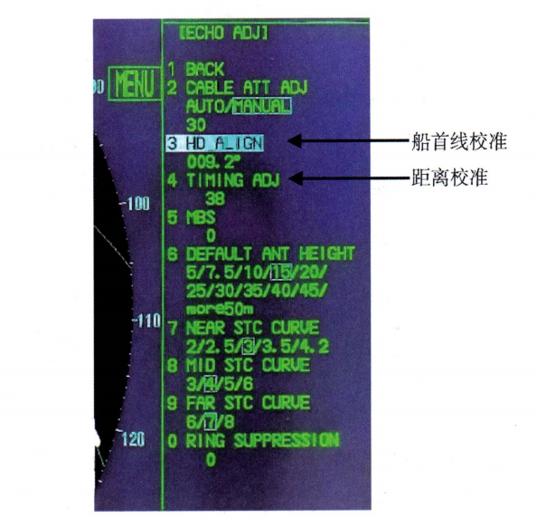
- (2) Parameter adjustment: Refer to the radar technical manual, adjust the trigger delay correction distance error (TIMING ADJ) according to the specified steps, as shown in Figure 1-3-1.

Figure 1-3-1 FURUNO FAR-2××7 Series Radar Error Calibration
- (3) The remaining error needs to be verified after adjustment to confirm that the radar ranging error meets the standard requirements.
(ii) Harmonization of public datum errors
Radar measurements of target range, bearing and other tracking data are referenced to the Common Common Reference Point (CCRP). The Marine Radar Performance Standard states that if multiple antennas are installed, the radar system must provide a method of compensating for the positional deviation of each antenna. The radar CCRP deviation compensation setup must be completed during the initialization phase of the installation. Inaccurate amount of deviation compensation will result in an error in the target range measurement on the radar display relative to the CCRP.
Before setting, you need to calibrate the radar timing error, and then set and adjust the CCRP position according to the steps specified in the technical manual. Take Furuno FAR-2××8 series radar as an example, the operation of changing the reference position of CCRP is as follows: Use the trackball to move the cursor to the “REF POINT” indication at the top of the screen, and then left click to select [ANT] or [CCRP] according to the requirement. Where [ANT] means to use the radar antenna position as the reference position, and [CCRP] means to use the position of the driver's console comprehensive information display (CONNING) as the reference position.
(iii) Activity distance marker circle error
The radar is equipped with at least 2 VRMs for accurate measurement of the target range, and the VRM errors will directly cause the target range measurement to deviate. For PPI radars, the VRM error correction can be checked at any time, or at least once per flight or per month, whichever is shorter. According to the radar performance standard, the system accuracy of the RR should be 1% or 30m, whichever is greater, of the maximum range used.
II. Radar azimuth errors
The azimuth system errors include beam width error, pixel error, first line error, compass repeater error, common datum error, antenna main flap deviation angle and beam asymmetry error, etc. Among them, the beam width error, pixel error, antenna main flap deviation angle and beam asymmetry error do not require maintenance correction. Among them, the beam width error, pixel error, antenna main flap deviation angle, and beam asymmetry error do not need to be corrected. In the following, only the first line error, the compass indication error and the bearing error caused by the unified common reference point are introduced for the attention of the electrician and technician. The Radar Performance Standard states that, irrespective of the type of stabilizing sensor and transmission system, the accuracy of the radar display bearing correction should be within 0.5° when the ship's slew rate is in general conformity with the appropriate class specification.
(i) First-line error
The first line is a scanning line with enhanced brightness displayed on the screen when the main antenna flap is pointing parallel to the ship's keel. It is the datum line for radar bearing measurement, and its error will lead to the relative bearing and true bearing error of target measurement. The checking of the first line error should be carried out every voyage or every month (whichever is smaller) to ensure the accuracy of the bearing measurement.
- (1) Error Measurement: When the weather and sea conditions are calm, at berth or at anchor, choose the mode of relative motion of the first line upward, select the stationary target echo within the range of 0.125-0.25 n mile, and manipulate the EBL to measure the target's bearing. At the same time, the relative bearing of the same target is observed by radar and azimuthal sub-compass, and the error is calculated.
- (2) Parameter Adjustment: Refer to the instruction manual to enter the orientation adjustment menu, and adjust the first line error (HD A- LIGN) according to the steps until the relative orientation error is eliminated, as shown in Figure 1-3-1.
- (3) Error verification: After adjustment, it is necessary to confirm that the remaining error meets the standard requirements.
(ii) Indication error of the compass repeater
A compass repeater error will result in a fixed error in the radar headline and target true bearing readings. This is eliminated by comparing the radar compass repeater with the main compass bearing and adjusting the compass repeater to agree with the main compass. Checks for this error are normally carried out once a cruise or once a month, whichever is the lesser.
(iii) Harmonization of public datum errors
Inaccurate CCRP error compensation will result in an error in the target orientation measurement relative to the CCRP. To change the reference position of the Furuno FAR-2××8 series radar, move the cursor to the “REF POINT” indication and click to select [ANT] (antenna reference) or [CCRP] (cockpit CCRP reference).
Furuno FAR-2107/2807 Series Radar Initialization Calibration Example
Distance and first line calibration specific steps:
- (1) Press and hold [5:HL OFF] key while pressing the [1:HL OFF] key to enter the initialization menu (INITIALIZE).
- (2) Selection [2:ECHO ADJ] Enter the distance and first line calibration screen.
- (3) Selection [3:HD ALIGN] Calibrating the bowline error limits the error to 0.2° or less。
- (4) Selection [4:TIMING ADJ] Distance error calibration is achieved by adjusting the transmit delay.
Initialization setup parameters include: radar ranging and azimuth correction, antenna position, and comprehensive information display system (Conning) position. See Table 1-3-1 for details.
| menu | Submenu 1 | Submenu 2 | Detailed information |
|
ECHO ADJ | CABLE ATT ADJ | AUTO/MANUAL (0-73) | -AUTO: Calculates based on the noise level and automatically makes adjustments. -MANUAL: Manually adjusted to produce a small amount of noise. |
| HD ALIGN | (0°~359.9°) | First-line error calibration for correcting the orientation error of the target and its echoes | |
| TIMING ADJ | (0-4095) | TX delay tuning due to circuitry and antenna system transmission lines to correct for distance errors to the target and its echo | |
| DEFAULT ANT HIGHT | 5/7.5/10/15/20/ 25/30/35/40/ 45 m, More 50 m | Selection of antenna height from sea level |
|
OWN SHIP INFO | SCANNER POSN | BOW (0~999m) | Data indicating the position of the radar antenna in the ship's mark. It is also possible to make the radar antenna position a reference point |
| PORT(0~99m) | |||
| GPS1 ANT POSN | BoW (0~999m) | Set the GPS antenna position. This data is used to calculate the cursor position (latitude, longitude). interface of the GPS navigator is: -GPS1: Connect to the navigator interface; -GPS2: Connection to meter, tracking control, HDG, RS-232, local area network (INS) interface; See Figure 1-2-4 for details of the interface location. | |
| PORT(0~99m) | |||
| GPS2 ANT POSN | BOW (0~999m) | ||
| PORT(0~99m) | |||
| CONNING POSN | BOW (0~999m) | Set Conning Position to indicate the Conning Position in this vessel's mark. The Conning position can be set as a reference point for ranging, VRM/EBL markers, and cursors. | |
| PORT(0~99m) |









 Chinese
 English
 Korean
 Japanese
 Thai
Thai Arabic
 Spanish
 Russian
 Vietnamese
 Indonesian

