Understanding and Operating Distribution Panels and Distribution Boards
Against the single-line diagram of the power station simulator software system (as shown in Figure 5-1), point out the important equipment such as the main generator, main switch, busbar, etc., and find out the corresponding simulator hardware respectively.

In the power plant simulator software, open the main generator and the machine-side control box interface (shown in Figure 5-2), observe the various systems of the diesel auxiliary engine, through the machine-side panel of the instrumentation to understand the working status of the diesel engine. Compare with the generator machine-side control box in the hardware part of the power station simulator (as shown in Figure 5-3), to deepen the understanding.


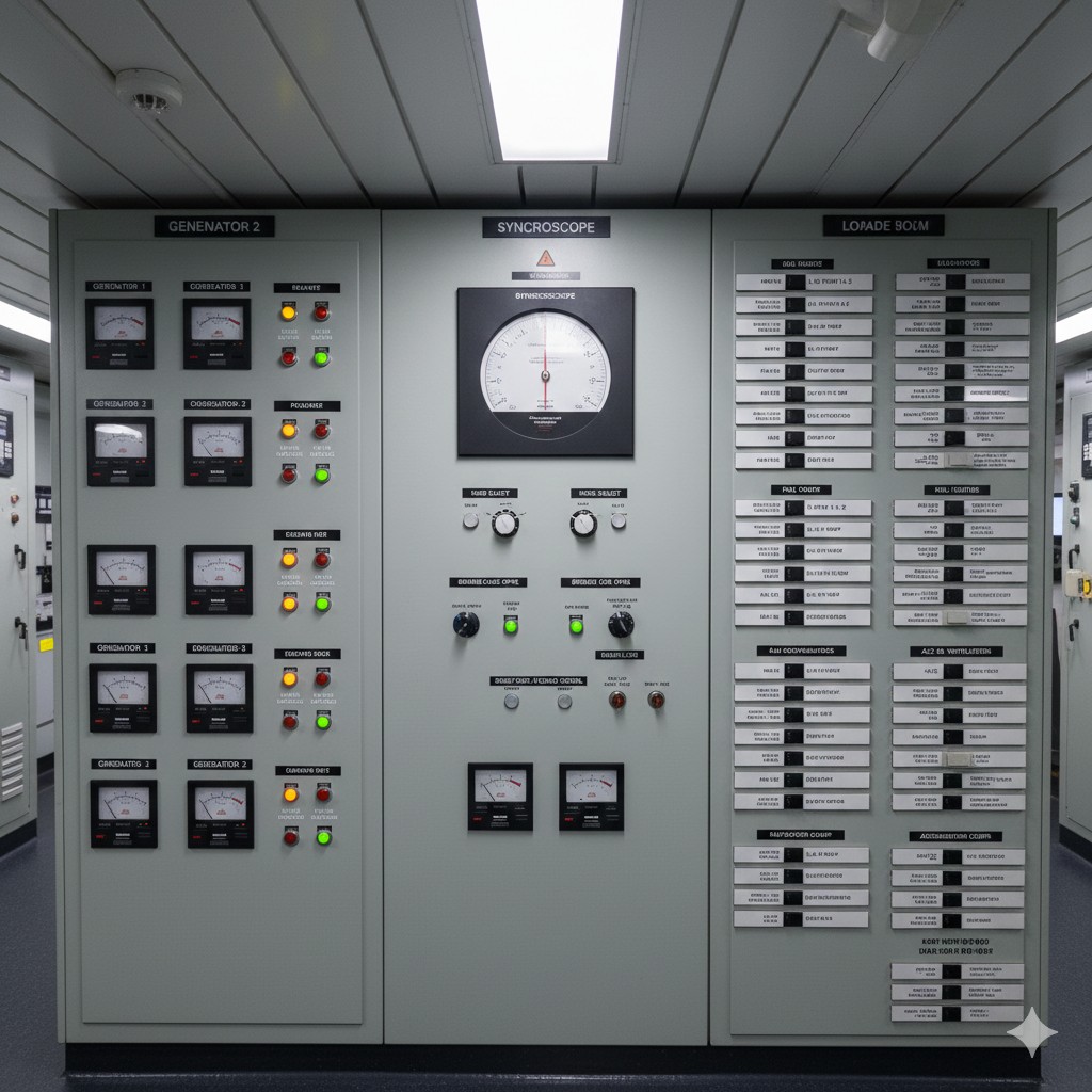
In front of the main switchboard (shown in Figure 5-4), which is part of the hardware section of the power plant simulator, observe the various components of the main switchboard: the generator control panel, the parallel panel, and the load panel.

For the generator control panel (shown in Figure 5-5), which is the hardware part of the simulator, the focus is on recognizing the “GEN. RUNNING” indicator, “READY FOR START” indicator, start button, stop button, close button with light, split button with light, voltmeter, ammeter, and frequency meter. lighted button, switch lighted button, voltmeter, ammeter, and frequency meter.

For the hardware part of the station simulator parallel screen (shown in Figure 5-6), the focus is on recognizing the synchronization table and switching switches, mode control switches, closing buttons, splitting buttons, and speed control switches.

For the load screens in the hardware portion of the station simulator, the focus is on understanding the location of the various load distribution switches.
II. Operation of switchboards and distribution panels
(i) Start-up and power supply operations
1. Pre-closing inspection
Verify that the generator has stabilized and that the voltage and frequency are normal. Check that the distribution panel circuit breaker status (open/close) and indicator lights are normal.
2. Closing operations
Close the main circuit breaker manually or by remote control and observe whether the voltmeter and ammeter values are within the rated range.
Critical action: Observe the grid insulation status immediately after closing the gate to ensure that there is no transient leakage.
(ii) Checking grid insulation status after load distribution and switching
1. Load shifting
The output power of each generator is adjusted through the load distributor to ensure a balanced distribution (the deviation is not greater than 10%). When switching important loads, the principle of “cut off first and then turn on” is adopted to avoid parallel short circuit.
2. Insulation condition monitoring after load switching
Within 5min after the load switching is completed, pay attention to the grid insulation meter, the insulation resistance cannot be lower than 1 MΩ.
III. Extension of knowledge
Within the Power Plant Simulator software, open the emergency generator interface and control box (shown in Figure 5-7) and observe the systems of the emergency generator, focusing on the startup subsystem. Familiarize yourself with the emergency generator machine-side control panel, the emergency generator control panel (shown in Figure 5-8), and the power distribution panel against the hardware and software.


Familiarize yourself with the battery and charge/discharge boards against the hardware and software, as shown in Figure 5-9.

Compare the hardware and software and familiarize yourself with the shore power box and the main shore power switch, as shown in Figure 5-10.

Observe and familiarize yourself with the physical aspects of the above sections in an automated simulator cabin.
IV. Relevant knowledge
1. Components of ship's electrical systems
A ship's electrical system consists of four parts: power supply, distribution unit, power grid and load.
2. Types of ship's power supply
The ship's power supply includes the main genset, emergency generator and batteries, and shore power can also be accessed through the shore power box in the harbor.
3. Types of ship's power distribution units
The ship's power distribution unit consists of a main switchboard, an emergency switchboard, a charging and discharging board and a shore power box, corresponding to the ship's power supply. Below the main switchboard, there are power distribution boxes and lighting distribution boxes for distributing power and lighting loads.
4. Composition and function of main switchboards
The main switchboard consists of a generator control panel, a parallel panel, a load panel and a busbar. The main switchboard is the operation center of the ship's electrical system. Its main functions are:
- (1) During normal operation, manually or automatically connecting or cutting off the power supply network from the power source to the power-using equipment, supplying or stopping the power supply to the power grid.
- (2) Measurement and monitoring of various electrical parameters of the power system (voltage, frequency, current, power, power factor, insulation resistance, etc.).
- (3) Adjusting the values of various electrical parameters of the power system (e.g., voltage, frequency).
- (4) When the power system fails or fails to operate normally, the protection circuit will automatically cut off the faulty circuit or send out an alarm signal.
- (5) Signal display of circuit status, switching status, and deviation from normal operating status.
- (6) For faulty electrical equipment to be repaired or under repair, when disconnecting the power supply at the main switchboard, a notice board must be hung on its corresponding switch to avoid electric shock or equipment damage.
- (7) Synchronization meter and megohmmeter on the switchboard are designed for short-term work, and the changeover switch should be triggered back to the zero position after the car or measurement is completed.
- (8) Observe the insulation of the ship's power grid as indicated by the megohmmeter or ground gas lamp on the switchboard. If the insulation is defective, it should be checked and eliminated in time.


